
Camera Mountings
Vinten Mk 3 Pan And Tilt Head
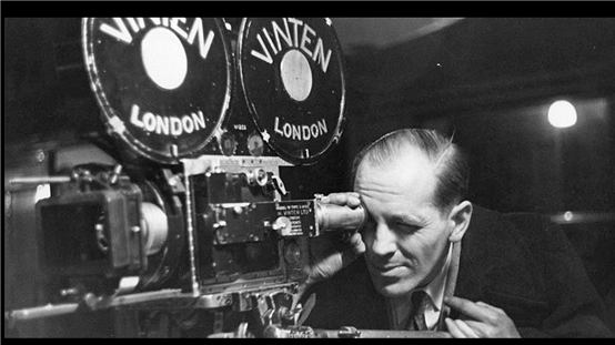
The television cameras of the time were heavy – ranging from about 250 lbs to about 400 pounds: they needed a suitable mounting. Here we introduce one of the most useful people in the television industry of the time – Bill (aka “Paddy”) Vinten.
The Vinten company was begun in 1909 by William Vinten senior, and initially manufactured Kinemacolor projectors.
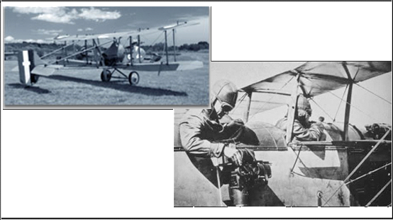
In 1914, the company workshops were taken over by the government and Vinten were invited by Sopwith at Kingston upon Thames to work alongside them in their aeroplane factory. This led in 1915 to an invitation by the Royal Flying Corps for William Vinten to design and build a special cine-camera for use in aircraft. Vinten developed the Model B – the first cine-camera that could be operated while hung over the side of an aircraft and as a result began to work in close co-operation with both the military and the film industry.
In 1928 Vinten expanded and moved to Cricklewood, North London, mainly supplying the film industry by creating specialised equipment for companies such as Kodak. By 1937 around three-quarters of all films shown in Britain were processed using equipment developed by Vinten. The company also had a strong presence in creating both sound and production equipment.
The Second World War created an increased requirement for reconnaissance cameras and military contracts secured world market presence for reconnaissance work.
In the late 1940s, the broadcast market began to flourish and Vinten developed the first telerecording camera. As a result the British Broadcasting Corporation became increasingly involved with Vinten. The BBC became the world benchmark for whom Vinten adapted many of their original film camera supports, creating equipment more suitable for television cameras.
In 1964 Vinten moved to Bury St Edmunds in Suffolk. In 1972, Vinten was floated on the London Stock Exchange, and in 1984 the company changed its name to Vinten Group plc. In 1995 the group rebranded itself as the Vitec Group.
Vinten Mk 3 Pan And Tilt Head

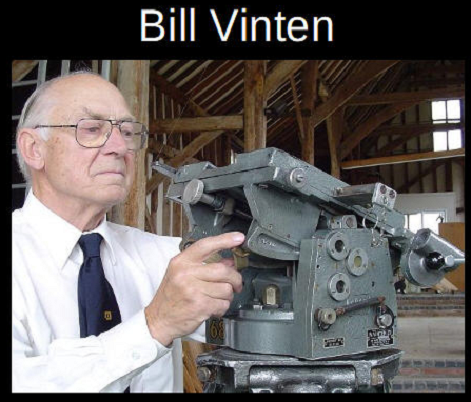
Bill (“Paddy”) Vinten, the son of William Vinten, who had founded the Vinten company, was a renowned cinematographer during and around World War II, and so he understood the needs of camera operators, translating his knowledge into remarkable products that transformed the industry. His Mk III was the first pan and tilt head to meet the BBC’s specifications for manoeuvrability.
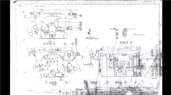
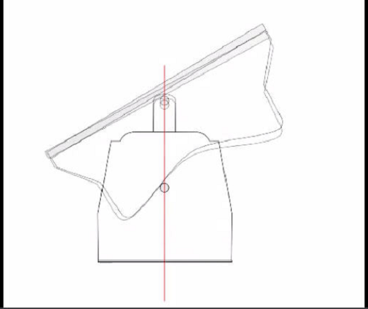
The Vinten Mk 3 Pan and Tilt head was engineered to maintain the centre of gravity of the camera acting down through the mounting. The head used risers and cams to maintain the centre of gravity. This made the tilting (pan up and down) of these heavy cameras considerably easier and, if correctly mounted, a camera could be left at any tilt angle without lock off. The design was highly innovative for the time.
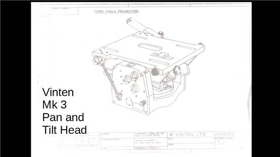
The basic principle behind the Vinten Mk III pan and tilt head is that if the centre of gravity of a load (the camera) remains in the same horizontal plane as it moves, it will stay in balance.
| Video Clip | |
| To see a video clip which was displayed with this slide, please click on the centre arrow below: |
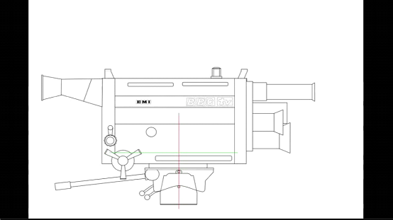
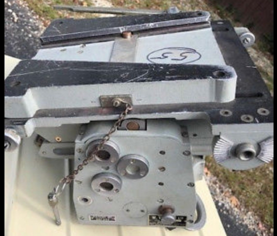
When this Pan and Tilt head first came into the BBC, there were three different cams (6″, 7″, and 8″) to cover the different Centres of Gravity heights of different cameras. The cams had cast-in raised numbers like 5, 7, 8 or 9 visible at the front. The higher number, the heavier and/or longer camera that could be supported.. The cams, two per pan head, could be changed for different camera types, from the light EMI Vidicons (in Presentation) to the very big Marconi colour cameras in Studio H, Lime Grove. The BBC eventually settled for 7″, which coped admirably with 4½” Image Orthicon Marconi Mk IVs, EMI 201 and 203s, and then the EMI 2001 4-tube and Phillips/Peto Scott 3-tube colour cameras. So, within each studio, the cams did not need to be changed. Fitting an Angenieux zoom lens on an EMI 201 black and white camera on a daily basis didn’t justify any cam change, for example, but it did change the centre of gravity of the camera and lens assembly – which might explain a lot of – er – issues! However, it was a different case for Outside Broadcasts: they may have used a higher number.
Video Clip | |
| To see a video clip which was displayed with this slide, please click on the centre arrow below: |
Between the panning head and the camera was the wedge plate. This wedge plate was essentially a quick release mechanism, a standard mounting for film and television cameras (note that the Vinten head could accept a screw fixing in preference to the wedge if desired).
Television studios TC2 and TC5 had four cameras. TC3 and TC4 had five cameras – but in each studio there was a live spare (a camera connected up, warmed up and lined up) ready to be swapped out for a failed camera at a moment’s notice: the wedge mounting allowed this to happen very quickly. Remove the pin, pull the slider, pull the camera back a little – and off the camera would come. (I actually saw an EMI CPS Emitron fall backwards off its pedestal just before a “Grandstand” – not sure why it happened!). In fact, for most of the time I was working as a Tech Op, studios TC3 and TC4 worked with 6 live cameras and no back-up spare.
The centre of gravity could be adjusted (within limits) by moving the wedge plate long the pan and tilt head using the knurled wheel (and by moving the camera along its mating part of the wedge plate used to secure the camera to the pan and tilt head). So, if a zoom lens, autocue, headlights, or whatever, was to be mounted on a camera (and thus changing its point of balance), the centre of gravity could be adjusted by shifting the whole lot, back or forward, relative to the panning head. This plate position was adjusted while the camera was horizontal, and the pan and tilt head chains were still on. There was enough slack in the chains for an operator to find a near-enough balance position. Then the chains were taken off, and the adjustment tweaked, such that balance was maintained throughout the tilt range.
This didn’t always work out: on the original “Nationwide” – from Studio E, Lime Grove after refurbishment with EMI 203 Image Orthicons – someone decided to try front projection of slides (front axial projection). A projector was mounted on the side of the camera head, projecting via mirrors and the autocue glass along the axis of the lens. This severely restricted any decent camera head movement.
Another way this did not work out was with CHAR (Camera Head Attachment – Rocking). This was a plate which enabled the camera to swivel at right angles to the panning head, thus replaced the tilting action with a rolling action. The sliding plate was rendered ineffective, leaving no way of maintaining balance. As soon as it ceased to be horizontal, the camera it would topple out of balance and become a deadweight. Normally, a CHAR was used on the front of a crane, which meant that the cameraman could support the weight on his knee, and often they were hardly aware of the problem. If there was a CHAR on a ped, this was an untenable situation. The cameraman had to try to support the weight of the camera with one hand, while operating it with the other – particularly since the panning handle was off at right-angles, and the only way of maintaining headroom was by craning up!
There was a vertical plate on one side of the pan and tilt head that had a slot in it, following the cam profile, against which there were adjustable leather friction pads for the tilt operation (pan up and pan down). The leather needed a renewing dose of Dubbin every few weeks or months to stop it grabbing and thus giving a sudden jerky start to a camera move and yet providing enough “stiction” to hold the camera tilt angle steady without necessarily using the tilt and pan locks. Some cameramen removed all friction and some set it so it was relatively hard to move. Either way, or the middle ground, it was a good plan to balance the friction settings to give a smooth diagonal pan and/or tilt (vertical pan) move. This “Alter to your taste” friction adjustment was one of the Mk III pan and tilt head’s delightful features. Horizontal pan friction was also adjustable, of course, but cameramen never actually saw its workings: it was an adjustable metal band on a circular leather drum inside the base adjacent to the massive ball race (this was usually only seen by a mechanic doing a routine overhaul). It was less critical in its setting, perhaps because it was less exposed and didn’t dry out.
A later panning head, the Vector 70, only worked with cameras within a fairly narrow Centre of Gravity height range. The Thomson colour cameras had a relatively high Centre of Gravity – which was outside this range. The BBC rejected the Vector 70 because weights had to be added to the panning handle to bring the Centre of Gravity within range: this was a backward step to the days of weights balancing the original Autocues: in fact, the BBC cancelled orders for six Vector 70s. This had the required effect – Vinten quickly developed the Vector 70H which addressed the problem. The 70 series were not ideal as the pan drag lost all drag for more than 10 seconds if the cameraman panned more than 120º or so as it was a sectored system. That was a pig on the original National Lottery shows where the cameraman had to swing round to cover the audience, then back to the machine! The newer Vector 700/700H addressed that problem with a different drag system.
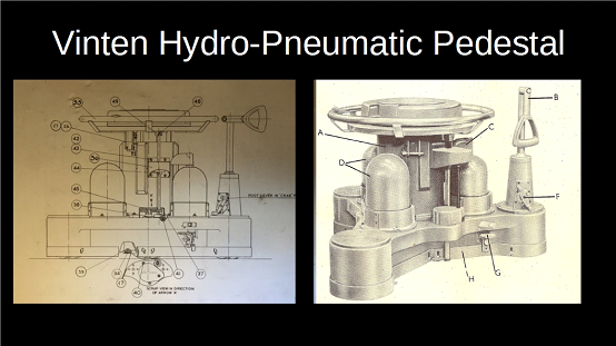
Vinten Hydro-Pneumatic Pedestal (HP)
The Vinten company features very largely in this account, as it not only provided a truly wonderful pan and tilt head, but also developed camera pedestals and camera cranes. The reason for camera pedestals and cranes is so that the camera shots can develop – an individual camera moves with – or against – the subject. Such a development shot – or camera movement – combines the functional purpose of keeping the main subject in frame as the subject moves from one position to the next (sitting to standing, turning, walking around the set), but which also includes some visual interpretation of the character’s style, movement and emotion. The camera is another “actor” in the drama.
Camera movement enhances the dramatic performances and the emotional involvement of the audience. The camera move should take the viewer into a new and hopefully exquisite composition. And with television in the 1960s it was done live or “as-live”,
The Vinten HP 419 ‘Hydro-Pneumatic’ gas-balanced pedestal was launched in 1957. This pioneering pedestal enabled TV cameramen to track and crane all at the same time without losing sight of the viewfinder. Many thousands of the HP 419 design were sold worldwide.
Video Clip | |
| To see a video clip which was displayed with this slide, please click on the centre arrow below: |
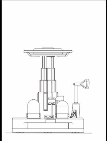
The sections of the pedestal worked together – they all rose or fell as one: there were no “cluncks” as each section took over, as they were interconnected by the single hydraulic system. All wheels and pinions on the pedestal were mounted in ball races.
There were three domes on the pedestal base, two for nitrogen gas under pressure and one hydraulic accumulator. Inside the four extending columns was a hydraulic ram connected in a closed circuit which included an accumulator: hydraulic fluid moved out into the rams higher up the pedestal.
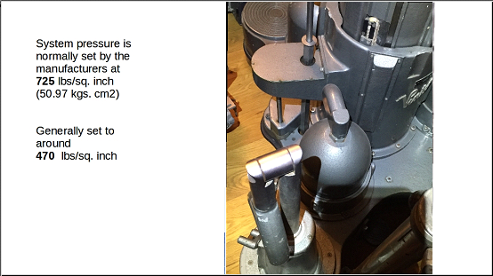
The oil in the accumulator was lowest when the pedestal was fully up. The nitrogen pressure (generally 470 lbs per sq.in) on the bladder filled with oil balanced the column (and camera). The weight of the camera pressing down on the ram pushed oil into the bladder – the oil itself was not pressurised: the only thing that gave balance was the nitrogen on the outside of the bladder. The camera and other equipment would always be balanced with two 4 lb. (2.04 kgs) weights in the tray, so that small items of additional equipment, different lenses, etc . could be fitted subsequently up to a total weight of 9 pounds. (4. I kgs.) and compensated by removal of these weights as necessary.
More nitrogen is pushed into the system for the heavier cameras – the maximum recommended pressure for efficient working if the pedestal was 725 lbs per sq in (50.97 kgs/cm squared).
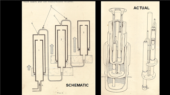
Vinten copied lots of off-the-shelf components from various sources. Some of the ideas were “pinched” from aircraft technology – e.g. from the undercarriage. The oil used was aviation oil (thin viscosity) as used in the aileron control, as this would not cause more friction.
The three moving sections all went up and down together, like a concertina – not in separate stages. There was also the steering rod which telescoped up and down alongside the column, but less smoothly. Sometimes one section would fall with an audible ‘Clunk’. Cameramen often wrapped camera-tape around the offending section to try and muffle the sound.
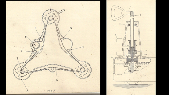
The pedestal was easily manoeuvred around the studio. Initially the pedestal just had a tiller which turned the wheels at one corner “steer”: if the pedestal had to move in a particular direction, the tiller was used to turn the pedestal so that the fixed wheels pointed in the required direction, the tiller steer wheels returned to the “straight ahead” position: the pedestal would now move in the right direction. However, the later version included a steering ring at the top of the column which, when the clutch on the tiller was engaged, was used to turn all the pedestal wheels in the same direction. This clutch can engage only at two specific positions (the pins that engage the tiller drive are located 180 degrees apart|).. Generally, therefore, when the foot changeover is actuated, the pins will not immediately engage and energy is stored in the compressed spring; as the steering gear is moved, a position occurs where the pins pick up their holes and the clutch inner assembly moves home.
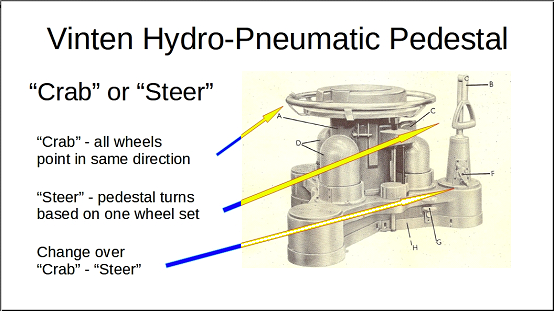
In this way, the steering mechanism provided two modes of operation – crab, where all three wheels turned together, and steer, where two wheels are locked in the straight-ahead position and the third wheel steered independently.
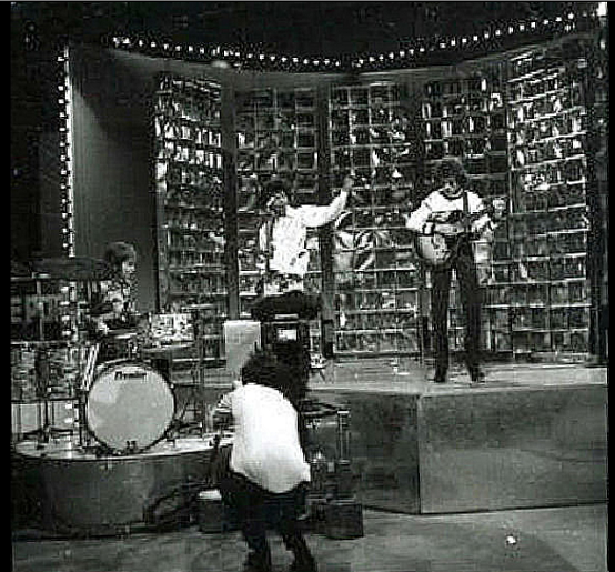
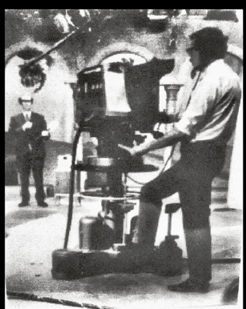
Here are some photographs of the HP pedestal in operation. The photograph of me during the first appearance of Jimi Hendrix on “Top of the Pops” only came to light in 2018, and was taken by a photographer on Jimi Hendrix’ entourage.
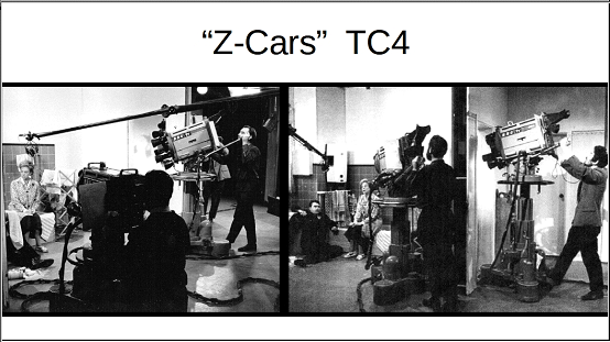
Pedestals on “Z-Cars”
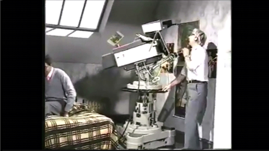
…and (possibly) me on an unknown – unremembered – programme:
Vinten Fulmar
After the HP Pedestal came the Vinten Fulmar (Vinten started naming their products after birds). This pedestal is actually still current. This is a pure nitrogen balance: it did not use hydraulic rams. As with the HP pedestal, there is a higher pressure of nitrogen to balance the heavier cameras.
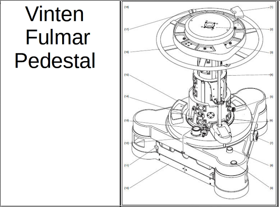
The major assemblies of the Fulmar pedestal are the telescopic column and the base. The telescopic column is located in a fixed tube secured to the base assembly, and consists of a three-stage extension unit and a two-stage ram. The ram is pressurised by nitrogen stored in a tubular tank and this tank forms the main structure of the base – creating a big reservoir of nitrogen.
The pressure of the nitrogen in the ram balances the weight of the moving parts of the pedestal column plus the camera and any accessories. When lowering or raising the load the effort applied to the column by the cameraman needs only to overcome the friction of the moving parts and the drag preset by the variable friction control. The column sections are linked internally by cords and chains running over pulleys and sprockets. This system ensures that all three sections extend or retract to the same extent.
To balance differing payloads, the nitrogen pressure is either increased or decreased as required. Fine adjustment of the column balance is by means of trim weights which are placed in a circular tray above the steering ring . Two storage trays are fitted to the base to hold trim weights which are not in use.
The pedestal can be easily manoeuvred around the studio. The steering ring is used to turn the pedestal wheels and the steering mechanism provides two modes of operation – crab, where all three wheels turn together, and steer, where two wheel units are locked in the straight-ahead position and the third wheel unit steers independently.
Each wheel unit consists of an alloy housing supporting a twin-wheel axle assembly. The wheel pivot is supported in a pair of ballraces and the upper end of the pivot shaft terminates in a sprocket assembly for the steering mechanism which links all the wheels together by an endless chain. The wheels are rotatable through 360 degrees by means of the steering ring and both the crab and steer modes of movement are controlled by the steering ring, with changeover effected by foot-operated buttons mounted on the base.
The wheels are of cast alloy running on ballraces and each is fitted with a low friction, squeal-free tyre.
This is a shot of Ron Green doing a piece of developing camerawork – just what the ped was design to facilitate.
| Video Clip | |
| To see a video clip which was displayed with this slide, please click on the centre arrow below: |
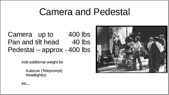
Camera up to 400 lbs
Pan and tilt head 40 lbs
Pedestal – approx – 400 lbs
So, an EMI 2001 colour camera, plus the Pan and Tilt head, plus the tray weights, plus the HP pedestal itself comes out to approximately 695 lbs: the cameraman were pushing around nearly one third of a ton!
 |  |  |