Camera Technology
Black and White Cameras
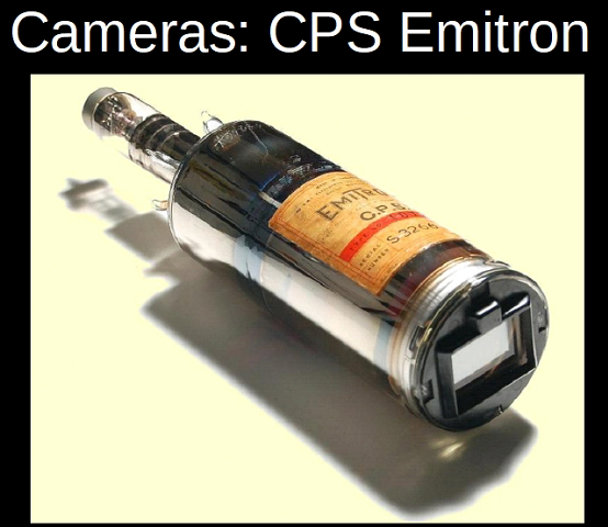
CPS Emitrons: Cathode Potential Stabilised Emitrons
The first TV cameras that I came across, on that first day in Lime Grove, were EMI CPS Emitrons. Cathode Potential Stabilised Emitrons.
The CPS Emitrons were introduced in 1956 into Lime Grove Studios – and were presented to the TV audience as the latest and greatest by Richard Dimbleby on an edition of “Panorama” (incidentally the longest running TV programme ever).
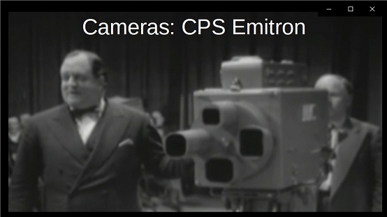
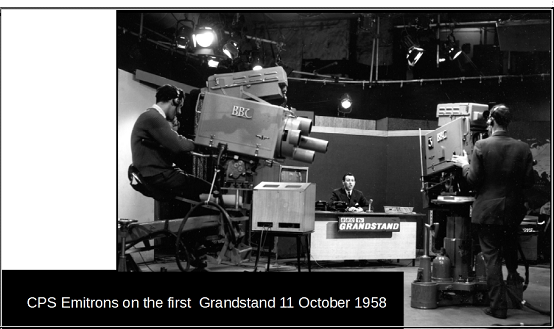
Lime Grove – and “Grandstand”.
Like all the original black and white TV cameras, the pick up tubes were variations on the Cathode Ray Tube, so both the image capture and image display used varieties of Cathode Ray Tubes. The CPS Emitron pickup tubes were sleeker than the original Emitrons (cylindrical design, some 14 inches long and 3.5 inches in diameter) but were really a straight line development of the original pick up tubes used in the first electronic television transmissions.
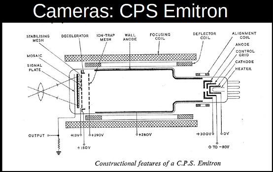
The target was a sheet of glass with a signal plate on one side and a photo-electric mosaic on the other: all elements were transparent. The mosaic was prepared by evaporating photo-electric material (tri-alkali mixture with a sensitivity of 60 microAmps per lumen) through a mesh that had 1000 meshes per linear inch: the mesh was then spaced 1 mm away from the surface and was used as a collecting mesh for emitted electrons.
This mesh – and the deposited mosaic – limited the resolution of the CPS Emitron tube to the number of mosaic elements (meshes) across the faceplate of the tube.
When an optical image was focused one the mosaic. photo-electrons were released in direct proportion to the light, and these electrons were removed immediately by the collecting mesh or wall anode. This meant that a positive charge was established on the mosaic, and this built up during the scan interval. During a scan (using a low velocity beam), electrons landed on the mosaic in sufficient numbers to neutralise the charge and restore the mosaic to its minimum potential. This induced an emf in the signal plate which was capacitively coupled to the mosaic elements, the output of the tube being developed across the signal resistor connected between the signal plate and the electron gun.
The CPS Emitrons gave very nice facial tones, but there were some issues with them. If you pointed at a TV Monitor in the studio, and if the image was a suitable size, this large amount of light could affect the camera tube response, and the monitor picture could fill the whole picture area. This characteristic made them very useful for standards conversion, where a television camera on one line standard looked at a monitor which was showing a picture of the other line standard.
The CPS Emitrons would also “peel” – the image peeled off as if it were a sheet of paper being peeled off a surface – depending on the light in the image.
The most interesting effect with the CPS Emitron was if it saw its own output on a TV Monitor – a video howl-round. Do you recognise this?
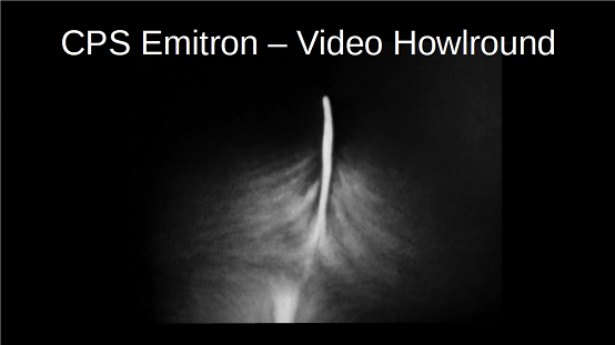
This howl-round was used in the title sequence of the original “Doctor Who” programmes.
| Video Clip | |
| To see a video clip which was displayed with this slide, please click on the centre arrow below: |
The CPS Emitron Mk 3 cameras had a relatively short lifespan. They were introduced in 1956 into Lime Grove – and by 1964 had been replaced by EMI 203 Image Orthicons.
I should note at this point that the TV Cameras described above and in the following paragraphs may properly be called the “Camera Heads”: each camera needed a Camera Control Unit in the Racks area (the Studio Engineering area, often located on ground level underneath the production gallery). The Camera Control Unit contained the bulk of the electronics to drive the camera – the camera “head” was useless without its Camera Control Unit (the CCU). The CCU included a large number of controls – most of which, when tweaked (according to one source), made the picture worse!
In the Vision Control Gallery in Television Centre (at least) the camera cables from the studio wall points terminated in a large inclined circular panel, from the centre of which radiated individual cables to the camera control units (a sort of glorified patch panel with thick cables). During the studio rig, the camera crew connected a camera head to a studio wall point. The Vision Control Operator (or any other designated person) connected the correct CCU cable to the appropriate wall point termination socket, so that Camera 1 on the mixing desk connected to the CCU that controlled Camera 1 on the studio floor. Some people called this patch panel the “octopus”.
Image Orthicon
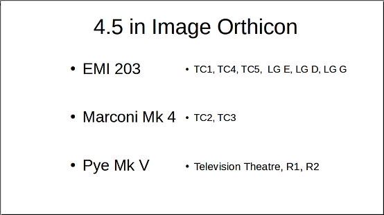
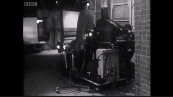
The other main production studio black and white cameras at this time were 4.5 inch Image Orthicons. Here is a Marconi Mk 3, at this time installed in Riverside Studios and the TV Theatre).
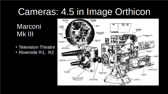
In all these Image Orthicon cameras, the pick-up tube was moved backwards and forwards for focus – there was no provision for focussing on the individual lenses.
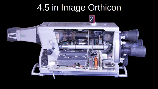
The Image Orthicon tube was developed at RCA. It represented a considerable advance in the television field, and after further development work, RCA created original models between 1939 and 1940. Rather than using the capacitance between many small elements and the signal plate, the Image Orthicon employed direct charge readings from a continuous electronically charged collector. The resultant signal was immune to most extraneous signal crosstalk from other parts of the target.
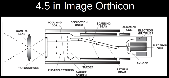
The front part of the tube contained an electron multiplier, which operated as a high-efficiency amplifier (an image intensifier). Images falling on the front plate emitted electrons which landed on the glass target. This was so thin that the electron charge could be read from the back side of the glass. High velocity light-induced electrons depleted the charge on the glass by knocking out electrons. The scanning beam put them back on each scan. The scanning beam then returned to the back of the tube, where it entered a five-stage electron multiplier. The missing charge in this return beam was the video signal.
The Image Orthicon tube was, again, a variant of the Cathode Ray Tube – and a picture could get imprinted or “stuck” on the tube (not quite as drastic as for the phosphors on the display CRT – remember screen savers on early computers?). To prevent the image from “sticking”, the scan coils included an “orbit” mechanism which moved the scanned area around the front surface of the tube. This Orbit was controlled at the camera.
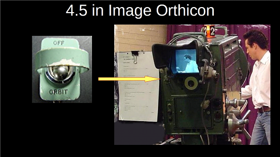
If the cameraman forgot to switch OFF Orbit on transmission, he was in for a dressing down from the Technical Manager (and/or others) at the end of the programme. If cameraman forgot to switch ON Orbit in rehearsal, he could sometimes get an image stuck on the tube: white on black captions were the main danger.
To get rid of the stick, the camera had to be pointed it at a bright evenly lit object, such as a soft light. This “burn off” did help the immediate problem but may have affected subsequent picture quality.
Another feature of the Image Orthicon tube was that a very dark (black) halo could be produced around the edges of a bright light, for example, a lamp caught in shot (car headlights as another example!) This apparently was due to electron scatter because of the very bright part of the image.
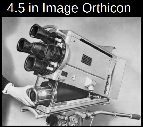
All the Image Orthicons had lens turrets. The Turrets contained four lenses to allow the camera to achieve a Wide Shot (WS), Medium close up (MCU), Close up (CU) and a big close up (BCU) without too much camera movement. Sometimes with mis-co-ordination between the Vision Mixer and the Cameraman, you sometimes saw lens changes on shot (although at least on one “Top of the Pops” it was done deliberately).
Camera focus was achieved by moving the tube assembly within the camera body: the lens turret did not move (and the individual lenses did not focus). The lens change mechanism and the focus mechanisms changed positions on the different cameras, but by the early 1960s the general positions of these controls had settled down to focus handle at the bottom right hand rear of the camera body, with the lens change handle above it near to the top right hand rear.
Except for the early EMI 203 cameras – originally this had a high forward focus handle halfway down the right hand side. This was given short shrift by the BBC. EMI came back with the camera with the focus handle at the rear which then matched the contemporary Marconi Mk IV and Pye Mk V cameras (more or less) as being the “proper” place for a focus handle (the CPS Emitron predated the EMI 203 by years with a rear mounted focus (although this was on the left). There was a blanking plate in the abandoned position on EMI 203 BBC production models.
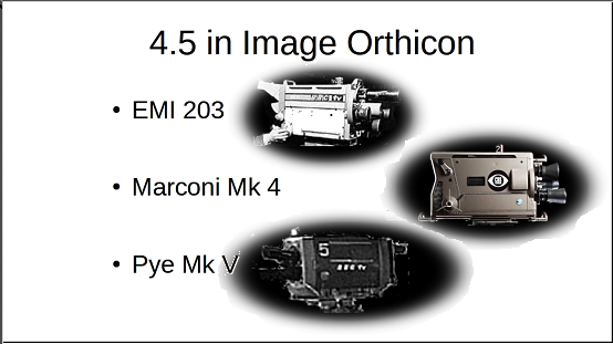
4.5 inch Image Orthicons cameras from EMI and Marconi were installed in the Television Centre when it opened, then in turn Riverside Studios and the Television Theatre were upgraded with Pye Mk V cameras (with a motorised turret)– and then finally the Lime Grove Studios with EMI 203s.
The BBC had to buy from all suitable suppliers. If the BBC Research Department came up with an improved product, the BBC were not allowed to manufacture it: a case in point was the STC 4038 microphone which was a BBC design.
Trivia: The Image Orthicon tube was at one point known colloquially in the States as an “Immy”.
Harry Lubcke, the then-President of the Academy of Television Arts and Sciences, decided to have the award for excellence in the television industry named after this nickname.
Since the statuette was female, it was feminized into “Emmy”.
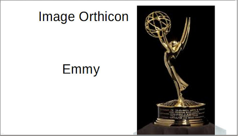
First awarded: 25 January 1949; 71 years ago.
Line Up, PLUGE and Vision Control
In any studio, the cameras had to be set up to give the best picture quality – and be set up so each camera matched the others in the studio. In the half-hour before transmission, the cameras, sound systems, telecine – in fact, the complete transmission circuitry was checked for correct operation: this was called “Line Up”. For sound, for example, a 1000 Hertz (cycles per second) tone was sent, and should read 4 on the BBC’s Peak Programme Meters all along the transmission path. In the days of analogue sound, the PPM indicated something close to the peak amplitude of the input signal, whereas a VU (“volume units”) meter shows an averaged signal level and gives an impression of perceived loudness).
Image Orthicon setup was as much art as science – the tube had a narrow optimum temperature range for operation (the camera had to be warmed up before use), and many of the electrical and magnetic field adjustments affected each other. On live transmission – where possible – there was a live camera ready for use as a standby, usually sat on a trolley of some sort. On “Softly Softly”, though, for example, there was no spare camera – all six were in use.
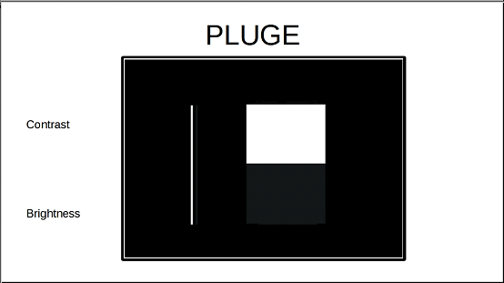
For the picture circuits, PLUGE was used: Picture Line-up Generating Equipment. There was a PLUGE for the cameras, so during the half-hour line-up all the cameras were checked by the Studio Engineers (also known as “Racks”). The Vision control operator (see later) checked all the monitors for correct black level and gain – basically brightness and contrast Black level was checked both on the monitor (so that the nearly black bar was just about visible) and on the oscilloscope (so that the nearly black bar was just above the black level “pedestal” on the waveform) Contrast was checked on the monitor by winding up the contrast until just before the lines defocused, and then this was checked with a photographic light meter. Telecine lined up using a film loop of test card “C”. All the vision lines were checked for correct amplitude (1 volt peak to peak signal level) and that the step from the sync level to black level (the “pedestal”) was correct and so on.
In a multi-camera set up, it was important not just to have each camera set up correctly, but that each camera matched the others – especially on facial tones. All cameras could be adjusted for aperture, black level and gamma by Vision Control.
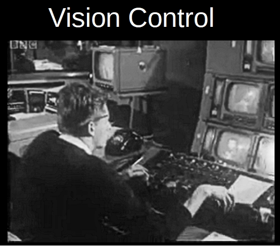
The Vision Control operator had a control for each camera (and the spare) so that was six controls in TC3 and TC4. Each control was on a quadrant, forward and back, which opened or closed the iris on the lens – this iris was driven from a motor mounted in the centre of the lens turret on all the Image Orthicons of the time (Marconi Mk III and Marconi Mk IV, EMI 203 and Pye Mk Vs.). The controls could be rotated – this adjusted the black level. And by pressing on the knob, the picture of that camera was sent to a preview monitor. As all the monitors had slightly different characteristics, this preview monitor was used to “eyeball” the picture match from camera to camera. Anyway, the Vision Control operator had a monitor for each camera, next to which was mounted a vertical oscilloscope on which was displayed a compressed trace of the picture waveform. The idea was that the operator checked the waveform for the black level – black in the picture should be just above sync level, on the waveform “pedestal”, and then check for gain – make sure that there was no clipping of the whites in the picture. These controls were very roughly analogous to “brightness” and “contrast” in the picture. Above each quadrant control on the desk was a rotary control for the gamma correction – change the relative amplification of parts of the waveform – stretch the backs, compress the whites. Of course, picture quality on the preview monitor was most essential, so part of line up was to put the test image (white and black rectangles) on the monitors and check the peak white output using a light meter.
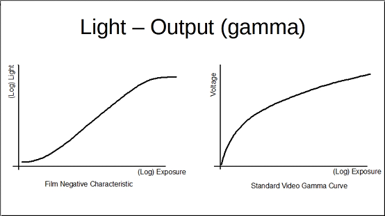
There were also similar controls for 2 VT machines and 2 TK machines. However, picture matching to a film insert was a losing bet – the different gamma characteristics for the television pick-up tubes and negative film stock made it just about impossible ever to match Black and White film inserts to the studio pictures.
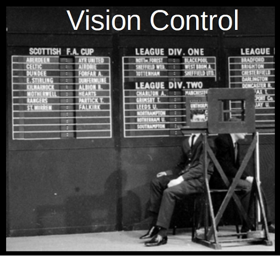
Setting up the black level and the gain of the cameras was particularly important when captions were to be used.
The Saturday football results, for example, were boards into which the names of the teams and the latest scores could be displayed – the scores were entered from the rear and could be changed while on air – but the camera output was adjusted so that you could not see the joins – or rather the gaps and recesses which are evident in this angled shot.
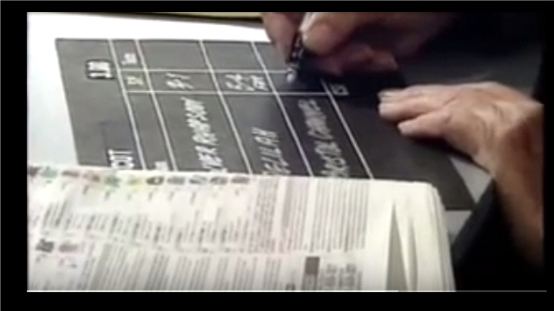
Black and white captions were used in every television show – a typical example was the roller caption superimposed over a picture at the end of the show – or the betting on horse racing:
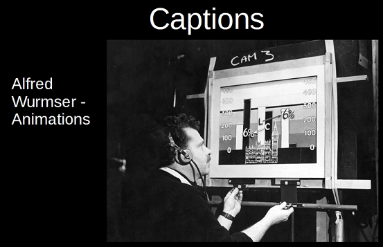
During a programme – especially “factual” programmes such as “Panorama” and Schools programmes – there would be animated captions.
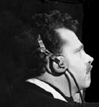
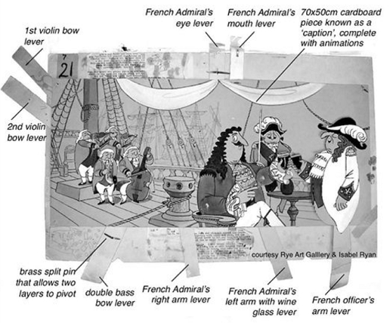
Alfred Wurmser was the great exponent of these animated captions, in which layers of card would be moved by control levers around the edges of the area in vision. Vision Control had to adjust the camera output so that the shadows of the layers were not visible and so that the various layers looked as if they were one single sheet.
A very similar technique was used by John Ryan for “Captain Pugwash”. Trickier Vision Control here, as the backgrounds were not black!
Vidicon
In the Presentation Studios A and B in the Television Centre, the cameras used Vidicon tubes. These were considerably smaller than the CPS Emitrons and the Image Orthicons: the tubes were one inch in diameter and about one-third of the length.
The tube functioned in a similar way to the CPS Emitron.
The Vidicon is a storage-type camera tube. it consists of a glass envelope with an optically flat face plate . A photosensitive, target plate is constructed on the inner side of the face plate. The target plate has two layers. To the front, facing the face plate, is a thin layer of tin oxide. This is transparent to light but electrically conductive. The other side of the target plate is coated with a semiconductor, photosensitive antimony trisulphide. The tin oxide layer is connected to a power supply of 50V.
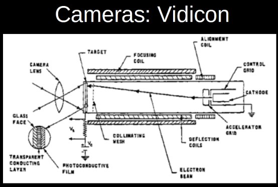
As with the other tubes, the electron gun’s emitted electrons are accelerated and focussed on the photo conductive layer by the grids, and vertical and horizontal deflecting coils, placed around the tube, are used to deflect the electron beam for scanning the target.
The light from a scene is focussed on the target. Light passes through the face plate and tin oxide, incident on the photo conductive layer. Due to the variations in the light intensity of the scene, the resistance of the photo conductive layer varies. The emitted electrons from antimony trisulphide reach the positive tin oxide layer. So, each point on the photo conductive layer acquires positive charge. Hence, a charge image that corresponds to the incident optical image is produced. As the electron beam from the gun hits the charge image, a drop in voltage takes place. As a result, a varying current is produced. This current produces the video-signal output of the camera.
In the early to mid 1960s, the BBC did not regard the 1 inch Vidicon tube as generating fully acceptable broadcast standard video, but as the continuing development of the tubes allowed the Vidicon to generate better video responses , the BBC started to use them in certain, limited, situations.
The Vidicon cameras in Pres A and Pres B (EMI 201 cameras) (Pres A did the Weather, Pres B did “Late Night Line Up”, original versions of “The Old Grey Whistle Test” and many other bits and bobs) had lens turrets like the main studio cameras.
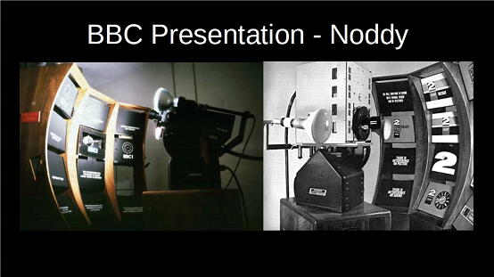
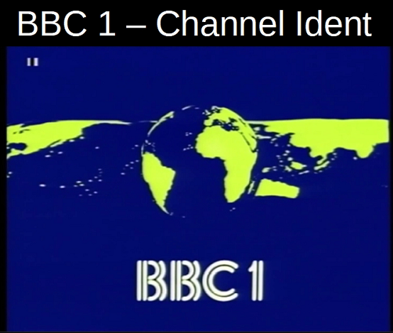
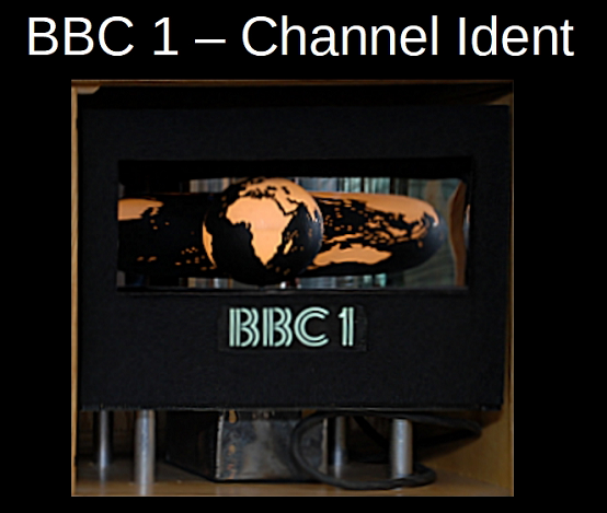
Vidicon tube cameras (usually with a single lens) were used for presentation captions – the Noddy cameras for Presentation and Network Control, for example, and the cameras used to show the mechanically driven station idents for BBC 1 and BBC 2.
| Video Clip | |
| To see a video clip which was displayed with this slide, please click on the centre arrow below: |
| Video Clip | |
| To see a video clip which was displayed with this slide, please click on the centre arrow below: |
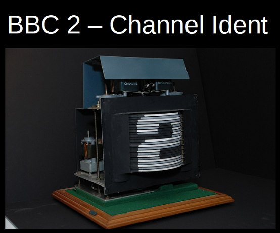
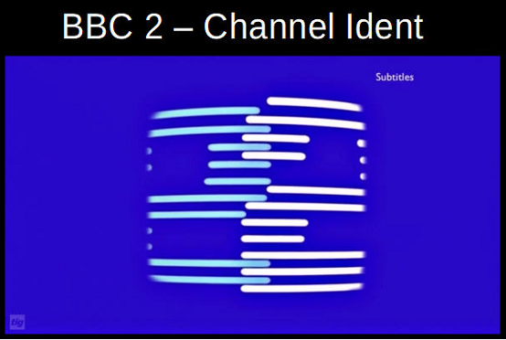
This mechanical Station Ident for BBC 2 was last used in April 1979.
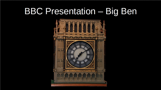
And, of course, the BBC had a model of “Big Ben” clock face for use on New Year’s Eve in case the weather was so bad you could not get a proper shot of the clock.
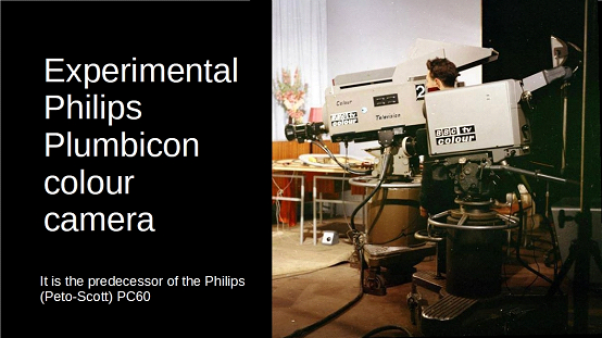
The Vidicon tube spawned various new types of tubes produced using different materials for the photoconductive layer – a popular one was the plumbicon, produced by Philips. These tubes had much better response characteristics.
Colour Cameras
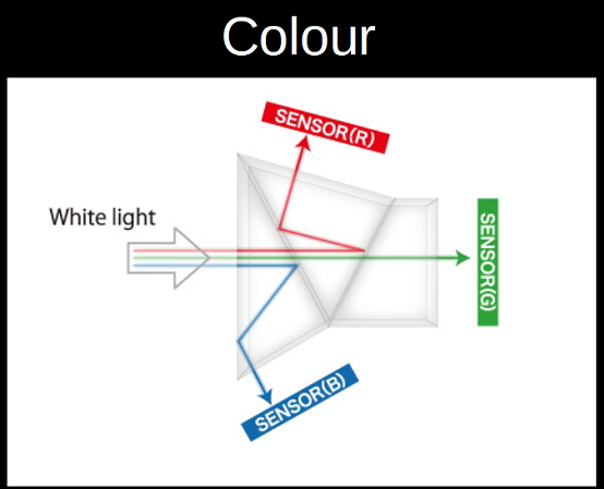
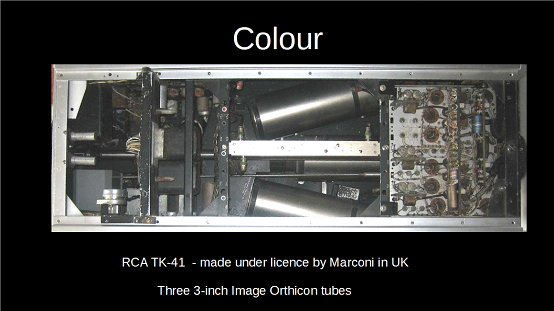
The original production studio colour cameras were essentially three black and white (monochrome) –Image Orthicon cameras stuck together (often 3 inch IOs), using dichroic mirrors (later, dichroic prisms) to first separate out the blue image, then the red image, leaving the green image to go straight through.
Later camera included a luminance tube (essentially a Black and White camera generating the luminance signal). These IO based cameras were enormous. The BBC used a version of the RCA TK40/41, the Marconi BD 848 colour cameras. Initially these cameras used a lens turret with four lenses. The issue here, of course, is focus: difficult to move the pick-up tubes to focus the images.
Each “colour” image was seen by an Image Orthicon tube, and the signals were combined from Red, Blue, Green to YUV, of which “Y” (“luma”) is the brightness, or lightness, of each part of the picture, and essentially is the black and white image (and is, in effect, R + B + G (and black and white TVs only decoded this Y part of the signal)). “U” and “V” are the Chrominance (or Colour) parts of the picture (“chroma” or C for short): “U” is Blue minus Luma (B − Y) and “V|” is Red minus Luma (R − Y). The idea of transmitting a colour television signal with distinct luma and chrominance components originated with Georges Valensi, who patented the idea in 1938.
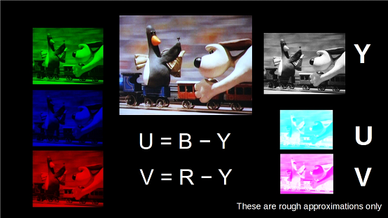
Please note:The U and V pictures shown here are not accurate: they are intended to show in a very general way the sort of result that is obtained.
After years of trials in Ally Pally Studio A, then later in Lime Grove Studio H, BBC transmitted in colour from 1st July 1967 – from Wimbledon! Britain was the first country in Europe to offer regular programming in colour, and by December 1967 some 80% of BBC 2’s output was colour.
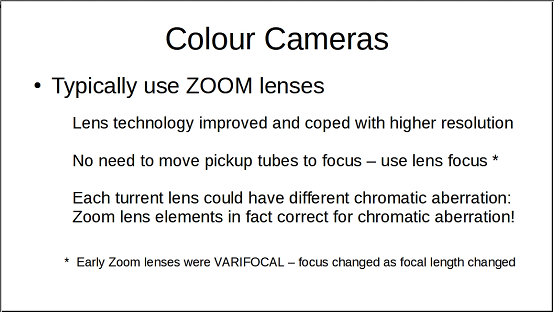
As colour came in, the cameras used improved Vidicon type tubes (like the Plumbicon) – and used zoom lenses. Firstly, zoom lenses were improving all the time: as there was just one lens, cameramen (and now camera ladies) would not be caught changing lens on shot (but they might get caught on a crash zoom), and of course, the focus could be achieved in the lens itself – but there was another technical reason as well. It was difficult to colour match across all four lenses on one camera (due to chromatic aberration and so on), let alone across four, five or six cameras!
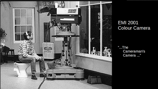
The favourite colour camera (as far as cameramen were concerned) was the EMI 2001. This actually was a FOUR tube colour television camera – the fourth tube was for luminance – essentially a monochrome television camera in its own right. The picture by Bob Glaister shows Steve Cockayne on the job…
When Colour Television came in, the black and white PLUGE was not very useful. To line up facial tones correctly – which is most important for Television – there was the CLUG (Colour Line Up Girl) – a live lady. Later, the Line-Up ladies (the live ones) were known as Studio Line-Up Girls (SLUGS): often they were trainee makeup assistants. The CLUG was a (necessarily) pretty make-up girl who had to sit patiently with all cameras pointing at her for colour matching. Eventually the CLUG was replaced by a very expensive still with many degrees of colour: rumour has it that, in the interests of colour accuracy, the picture was printed using 19 ink colours, not just the normal four.
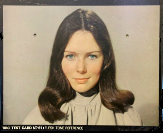
The name of the young lady used for the photograph is Lynne. At the time that the photo for the chart was taken (around 1977), she was secretary in the general office of Television Training Department, then based at Woodstock Grove. Incidentally, the photo version is still in use at the BH newsroom to line up the balcony camera used for remote interviews. It may well be used in the other studios as well.
Inlay and Overlay
Inlay is a technique where a third camera is used to generate a switching signal to switch from one camera output to another: often this was sued for wipes or “iris out”s (or “iris in”s). Inlay could be used in many different ways, but was generally a way of making a different sort of change of shot from cutting or mixing,
Overlay is a technique where the output of one camera is used to switch from another camera to itself. In Cinema, a similar technique is known as “travelling matte”, where the picture of one sequence is used to make a mask which is then used to mask another sequence during the print, allowing the first sequence to be printed into the gap left by the mask.
In television, this “overlay” is much easier to do, since it is an electronic switch, and with colour television it is even easier: the switch is generated by the presence or absence of a particular colour – usually blue or green – which is not present in any facial tones (in particular).
But what happened in the days of Monochrome (Black and White) televeision?
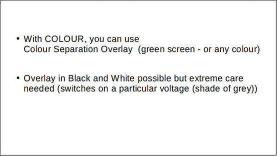
In the black and white days, there had always been Overlay (nowadays called Luminance Overlay), but the electronic switching was based on the black and white image. Often the switch was made at just above black level (but care was needed, since if there was any equivalent black in the overlaid picture, this would show up as “holes”). Note that there is a difference between (Luminance) overlay and Superimposition. Superimposition (“Superimpose”) combines the outputs of two cameras through the studio mixing desk. The two video signals are added together. A typical use for a superimpose is to show a caption. If this is printed in white on a black card, the white of the caption adds to the combined video signal and so shows as white. The black areas do not add to the video signal so preserves the output of the other camera. In overlay, however, the second camera switches the video output to itself on a line-by-line basis – and uses the grey tones of its own video output – before switching back to the original camera video output
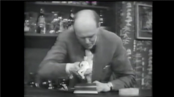
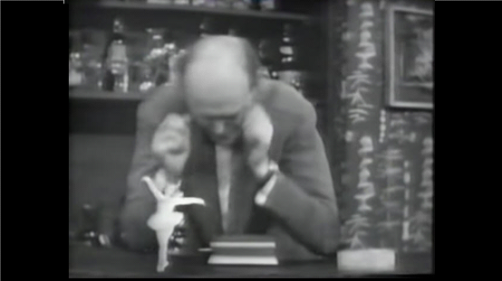
(Luminence) Overlay was used in a number of programmes for special effects. In these shots, David Nixon is working with a tiny ballerina. (Still shots are shown here – the original video reproduces rather jerkily) The ballerina was dancing against a completely black background, the camera showing a very wide shot.
Nowadays one very common use for Colour Separation Overlay (and its equivalent in the Cinema) is to provide a moving background to actors in a static foreground shot. Luminance (B/W) Overlay in this situation is not practical, so Back Projection was used.
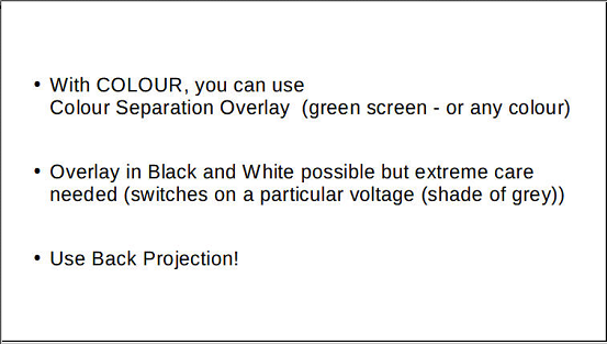
An Arc light cinema projector projected film to the back of a translucent screen. To get the necessary “throw”, the projector image was reflected from a very large mirror.
| Video Clip | |
| To see a video clip which was displayed with this slide, please click on the centre arrow below: |
One problem with back projection was where the director wanted to cut to the shot being shown on the BP: one programme where this happened was on “It’s A Square World” where actions were done in BP but were then cut to. Telecine had a run up of something like 8.5 seconds: the back projection projector was more like 10 seconds. It was sometimes difficult to co-ordinate the two displays (and of course, there were two prints of the scene – one on Telecine and one on BP. Later, the problem was resolved using an Eidophor projector for BP. This displayed the telecine output as a back projection.
Track Versus Zoom
We have already mentioned Zoom lenses in connection with the colour cameras.
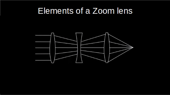
The basic elements of a zoom lens comprise a convex lens to focus the light (as for a normal lens). The middle element is a concave lens that spreads the incoming light followed be a final element that gathers the light and focuses it on the target. In a zoom lens, these elements are unlikely to be single lenses, but combinations of lenses to produce the required effect, As it happens, the first two elements – a convex lens followed by a concave lens – correct for chromatic aberration, although most likely these two elements – a convex lens made from glass with one refractive index (for example, crown glass with a low dispersion) followed by a weaker concave lens with a different refractive index (for example, flint glass with a high dispersion) – would be combined into an achromatic doublet as one element of a zoom.
| | Video Clip |
| | To see a video clip which was displayed with this slide, please click on the centre arrow below: |
With a turret camera, if you wanted to make the image larger on shot, the camera had to move in closer. In the film industry, cameras were mounted on dollies (wheeled platforms) which ran on temporary tracks – and so the term “track” was used to indicate a camera moving in – or out: track in and track out. TV cameras were mounted on dollies that were not mounted on rails, but the same term was used: we tracked in or tracked out – it was a tracking shot. Curiously, in the film industry, this tracking shot is called a “dolly shot”.
By the mid nineteen-fifties, “zoom” lenses were being used in television – starting with outside broadcasts (Zoom is simply an onomatopoeia (sounds like it does! Basically echoing sounds. The verb was attested in 1892, noun in 1918 and interjection in 1942). The most impressive early TV Zoom lens was the VAROTAL III, from Rank Taylor Hobson from UK, built in 1953. There was a slow uptake of zoom lenses, with early designs being considerably inferior to contemporary fixed lenses in terms of lens aberrations (and incidentally way more expensive and complex) and were usable only with a narrow range of apertures (f-numbers). These original zooms were not really zoom lenses at all but were actually varifocal lenses (for each change of focal length, the focus has to be changed). This meant that the zoom really had to be set up for each shot. Basically, the lens focus was set to infinity and the camera pointed at something as far away as possible. The tube was then set to get the image in focus, and then the tube movement was locked off. The zoom could then be pointed at the real subject, and the image focussed using the lens focus. But any change of focal length meant that the zoom focus had to be changed (in practice, the focus was set for the maximum zoom in on the subject). A true zoom lens, also called a parfocal lens, is one that maintains focus when its focal length changes. This is how modern zooms work – but in the 1960s the zooms were varifocal. This made some shots very difficult – “Play School” clock was one example – you had to focus on the clock, zoom out, then zoom into the toys on the roundabout, which was a different distance from the front element of the zoom. And then sometimes the tube slipped along its rack inside the camera … ,bp> There is a considerable differences between a track and a zoom. – Track and Zoom (and why do it)
Trivia: In the Film industry, the camera dolly is typically mounted on tracks, but the movement towards or away from the subject is termed a “dolly shot” (and is managed by grips or wranglers). In Television (in the BBC) the camera dolly runs free on the studio floor, and the movement towards or away from the subject is termed a “tracking shot” – a “track in” or a “track out”. The dolly operator is typically called a “tracker”.
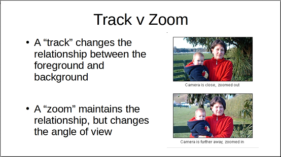
A dolly shot or tracking shot not only changes the size of the foreground object, but changes the relationships between the foreground, middle ground and background objects. A zoom changes the size of all parts of the picture in the same proportion, and does not change the relationships between the various parts of the picture.
The differences between a track and a zoom can be exploited, by doing both a track in and a zoom out at the same time (or track out and a zoom in at the same time). The foreground object remain the same size, but the relationship between the subject and the background changes. This can be exploited to good effect.
Now, the “Dolly-Zoom” (as it called in the film industry) is really only practical in film: you have a focus puller, a camera operator, dolly grips and as many takes as you need: in Television, going live with a single cameraman trying to track and zoom at the same time, it is rather impractical – although given a chance, we did practice!
This first example is from “Lord of the Rings”. It may look like CGI, but it is a Dolly-Zoom.

| | Video Clip |
| | To see a video clip which was displayed with this slide, please click on the centre arrow below: |
Steven Spielberg used a Dolly-Zoom in more than one picture. This sequence is from “Jaws”. Here you see just the start of the shot and the end of the shot.
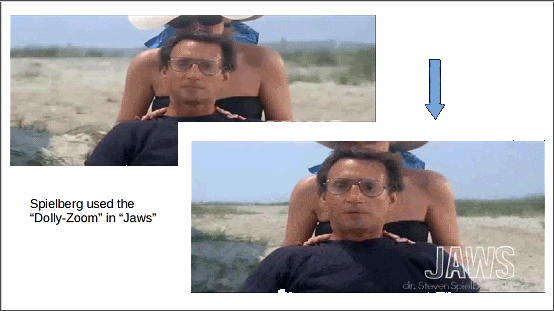
I personally do not think that it is very convincing, and, indeed, it is not very well done. The idea that Spielberg was trying to convey is Brody’s sense of repulsion with his inability to look away: and the fact that he has to do something and is basically alone. The beach widens behind him as he realises what is going on – and he is alone.
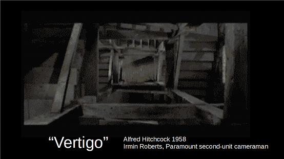
The Dolly-Zoom had its origins with Alfred Hitchcock and “Vertigo” (1958). The shot was developed by Irmin Roberts, a second unit cameraman with Paramount studios.
 |  |  |