Camera Cranes
And now we come to the Camera cranes…
Vinten Motorised
It is believed that the first crane shot came in 1916 on the D. W. Griffith spectacular silent film Intolerance. Griffith wanted to rise to the top of the Babylonian set and then descend to ground level again. He also wanted the shot to move into and out of the set.
Allan Dwan, an ex-engineer before getting involved with directing films, was contacted by Griffith. He built a large tower spanning two railway wagons. Dwan, in his own words, constructed “.. a device on a railroad track with an elevator in it. The device was very simple, built of tubing so it could easily be dismantled and put together. I … suggested the use of railroad tracks, made utterly smooth so there would be no vibration, and railroad wheels….”
So we get the word “track” for movement towards and away from the subject. This sort of crane needed a large number of wranglers or grips to operate. From this point, camera cranes – or dollies – became smaller and easier to use.
The ‘Edmonton’ crane was based on the 1936 Fearless ‘Panoram’ film studio dolly, and was built for the Rank Organisation, used mainly in British film studios. A version of this dolly, designed exclusively for television studios by Vinten, was called the ‘Pathfinder’.
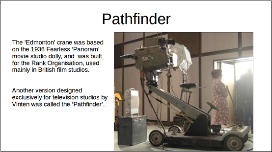
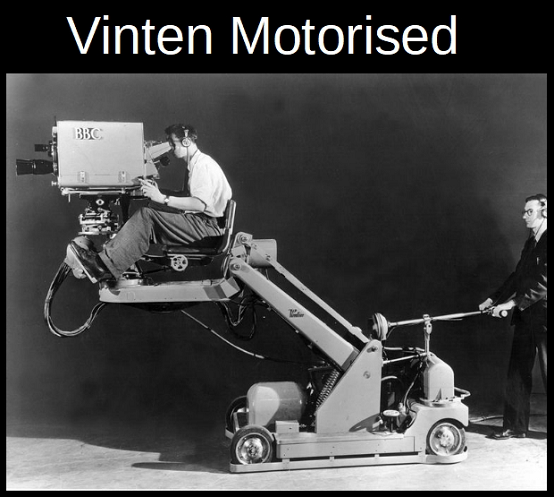
The Vinten “Motorised” was developed from the Pathfinder.
The Vinten “Motorised” was basically a crane arm or jib on a chassis. The arm was elevated by means of an electric motor with a worm drive onto a large pinion, the arm counter-balanced by huge springs. However, the construction of the crane limited the height that the Motorised crane arm could reach.
No one could claim that the elevation of the crane on shot was a seamless action.
The chassis had rear wheel steering, but these wheels were also powered by electric motors. As the wheels were turned to change direction, the speed of the wheels remained the same: the effect was that you seemed to get faster the tighter the turn. And the faster you seemed to go, the more difficult it was to correct! It was quite vicious.
As originally designed, the tracker drove it by walking behind the crane and steering it by a tiller which had a speed control on it. It was too easy to get the thing out of control. The tracker had to be careful setting the crane in motion because if he did it too quickly, the motors would swing violently to one side and he could easily have the steering handle ripped from his hands.
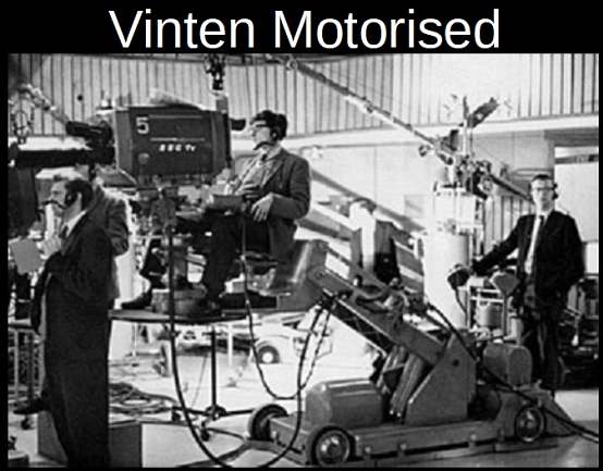
A platform for the tracker was then added to the rear, and the tiller replaced by a proper steering wheel. And a foot operated brake! However, it was still a vicious beast. The Motorised was used as the main crane on the old “Tonight” programme with Cliff Michelmore. A tracker (OK, me) was in constant fear of the back-end swinging round too fast and crunching into the fish tank that was part of the set.
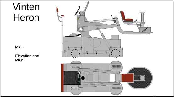
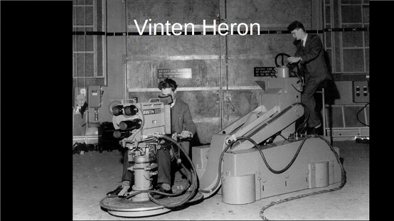
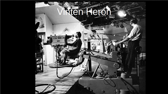
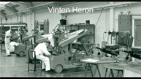
Vinten Heron
The Vinten Heron Camera Crane was designed specifically as a television camera crane and originally developed for the BBC in the mid-nineteen fifties (1955).
Using the experience gained for the Vinten Motorised, Vinten designed a hydraulically operated crane that would be able to crane up higher, would easily fit in a smaller television studio, and which would be able, also, to go in any direction. The ability to go fully sideways – to “crab” – made the Vinten Heron Camera Crane an extraordinarily flexible television camera crane, and the hydraulic system made it virtually silent in operation: it could perform for some time just on the pressure in its hydraulic reservoir. The reservoir was pressurised by an electrically driven pump, the electric motor running on 230 volts three phase AC (and not the more usual 415volts AC three phase).
The BBC bought models for its London and regional studios, and used the Heron Camera Crane on any and all productions, from “Captain Pugwash” (a live or “as-live” show with camera cranes looking down onto drawing boards on which the animators moved the characters) to music programmes such as “Top of the Pops” and “Best of Both Worlds” to situation comedies and serious drama productions.
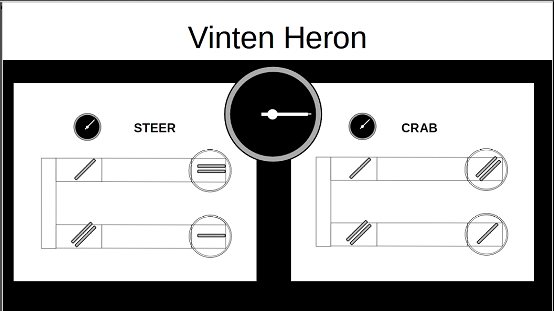
The biggest innovation in the Heron Camera Crane was its ability to crab (that is, to move sideways), thus allowing it to move freely in any direction, giving it the flexibility of a camera pedestal but with increased height, range and speed. The changeover from “Crab” to “Steer” could only be made when the wheel “tell tale” was in a straight ahead position.
This led to a particular “feature” of the Heron crane. In “Steer”, the steering wheel acted as a normal steering wheel – that is, to turn the crane to the right, the steering wheel was turned to the right. However, if the crane was in “Crab”, turning the steering wheel to the right made all wheels point to the left, and the Heron would move to the left. To go sideways to the left (wheels pointing 90 degrees to the left), the steering wheel was turned 90 degrees to the right. You soon got used to it.
The Vinten Heron television camera crane was a two-man camera “dolly” (for most of the time that the early versions of the Heron Camera Crane were in use in the television studios, the technical operations crews were nearly exclusively male.). The cameraman sat at the front with the television camera mounted on a Vinten pan-and-tilt head: in those days the television cameras were large and heavy, both the black and white cameras and the early colour television cameras. The Vinten Heron Camera Crane had to be substantial enough to “crane up” and “crane down” on shot (lift the cameraman and camera up and down with the pictures going out directly to the audience) without jerk, judder or hesitation. The tracker or dolly operator at the rear positioned the whole crane in the correct position, and then could track in or out, or crab left or right, again on shot, with a nice smooth action with no jerk, judder or hesitation. The tracker and cameraman could also make the crane do a figure of eight on the ground or in the air!
The hydraulic system and the steering mechanism were similar to those employed in the Hydro-Pneumatic pedestal. The steering to crab change over performed in an analogous way to the HP pedestals. The steering control was by means of chains – unfortunately no pictures of the chain routing. Like the pedestal, the Heron had no suspension., it relied on a perfectly level studio floor. Originally in the Television Centre, the floor were concrete topped with an asphalt screed, and one-quarter inch thick linoleum laid on top. The lino had squares and reference numbers marked on the lines, to match the rules placed along the studio walls.
The Heron Chassis was approximately 6 and a half feet long (with an overall length of some 11 feet 4 inches) and approximately 3 feet 5 inches wide over the cable guards (different Vinten manuals give some different measurements). For its reach and manoeuvrability, it was an extremely compact camera crane. The high mounting point for the jib arms meant that the crane could elevate to a high point – 6 and a half feet – without an excessive length of arm: the height could be increased by another foot (to seven feet six inches) with the extending camera mounting column.
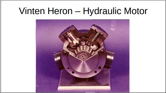
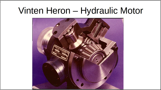
The Turning Radius was 6 feet 5 inches, making the crane very manoeuvrable. The chassis was mounted on six wheels. There was a single powered wheel at the front right and at the rear left: these wheels were driven by hydraulic motors. The smoothness of hydraulic drive allowed the Heron to track at very low speeds; full torque was always available at any speed. And no “speed up” effect as you turned – as the crane steered, it kept the required speed. At full speed the Heron travelled at about 12 ft per second.
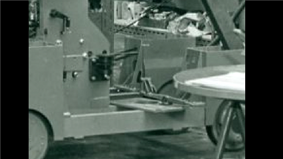
Here are pictures of the Heron under construction at Vintens:
The front left and rear right had a pair of wheels displayed around the central vertical pivot. These wheels were braked, the idea being that the braking forces were evened out.
A Pressure Gauge on the main control panel showed the pressure in the main hydraulic system. The gauge always indicated some value , and provided a quick check on the correct functioning of the hydraulic system. This system included an accumulator which maintained pressure in the system even when the motor driven pump was not running.
The pump could run Fast or Slow. On the control panel, a switch offered two positions, marked Pump Fast and Pump Slow which energised either of two windings on the double-wound pump driving motor, thus selecting either of two pump speeds. In Pump Fast mode, the normal setting, the pump ran at full speed until a pressure of 950 Ibs per sq in. was reached in the hydraulic system, after which the motor cut to the slow speed to continue building up the maximum pressure of 1060 Ibs per sq.in.
The output from the pump in this condition was entirely adequate to cover any combination of control movements possible, on a continuous basis. The electric pump could be a bit noisy at times, so the pump could be completely switched off, the power for movement coming from the pressure available in the accumulator. However, this could not continue for very long!
If a shot needed very slow, sustained movement, the pump could be set to Pump Slow: this held the pump at its slow speed, irrespective of pressure. This slower speed reduces the pump motor noise still further, which was useful if there was a scene which was very quiet and in which there was little camera movement. The pump had to be switched to Pump Fast as soon as practicable.
Power requirements: 230v 3 phase A/C. Yes, 230v 3 phase A/C. Power for the Heron was provided in every wall point around the studio walls: the wall points providing microphone sockets, talkback feeds, monitor feeds and power supplies of various voltages and frequencies.
Weight of the Heron (without camera and crew) was 2270 lbs.
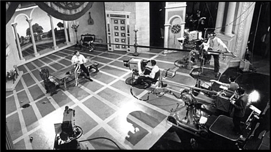
Here is a shot of the Heron in action. The video gives a little of the feeling of going live on air with “Z-Cars”.
| Video Clip | |
| To see a video clip which was displayed with this slide, please click on the centre arrow below: |
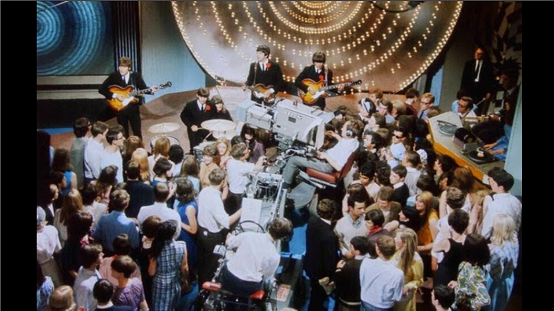
And this is what it could be like on “Top of The Pops” – often the tracker had to live up to the title “Dolly Operator” as he leapt off the back of the crane to get the girls to move out of the way …
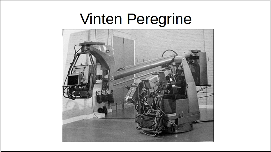
Vinten Peregrine
The Vinten Peregrine was a failed experiment in camera crane technology. Designed to a BBC specification (one part of which stated that the crane should be able to track through a standard door in a set flat.), it was delivered to Television Centre in 1965. The idea was to build a camera crane that would fit on the footprint of a Vinten ped, but have the range of a Mole (MPRC) crane and the flexibility of a Vinten Heron. It was designed to carry a standard sized mid-sixties monochrome camera equipped with an Angenieux zoom. It lasted a very short time and was hardly used at all.
The cameras of the day, both monochrome (Image Orthicons) and the original colour cameras, were very heavy, which in turn needed a massive cradle on the end of the jib arm. The existing servos weren’t up to the task, and the whole thing, a heavy mass on the “footprint” of a pedestal, was simply too heavy (it sank into floor of studio TC5 overnight, leaving a big round dent in the floor).
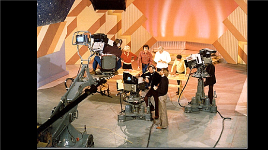
Why was it a failure? It was a large machine operated by clunky early sixties servos, with enormous flexibility of movement controlled by two people who were looking mostly at monitors low down in front of them (and less looking at their environment). It was a clumsy and somewhat dangerous “beast”.
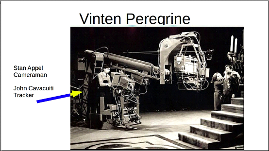
The cameraman was Stan Appel, and the tracker – who is seen more clearly in this – was John Cavacuiti.
The Peregrine cameraman had a “normal” zoom focus control (operated by his right hand) and that was about the only normal thing about the crane. To focus the camera, he had to use a Peto Scott monitor in front of him.
The zoom control was the normal Angenieux one where the whole grip rotated, anticlockwise to zoom out, clockwise to zoom in. This was operated with the left hand which also operated the tilt servos with a position control that mimicked a normal pan bar . The same “pan bar” also operated the pan controls but this was a pressure sensitive device, the more pressure you exerted the faster the pan and the “pan bar” did not actually move in the horizontal direction. Thus the cameraman’s left hand moved up and down to tilt, twisted left and right to zoom and pushed or pulled against an immoveable bar in the horizontal plane to pan. This pressure sensitive device caused actual bodily injury to one cameraman.
The tracker had five controls to choose from in order to place the camera in the appropriate position, plus a brake. The elevation was controlled by a positional control placed between the cameraman and tracker and operated by the tracker’s left hand. The idea was that this could be operated by either operator, but in practice it was found that the cameraman had more than enough to do! This control was pulled back to crane up and pushed forward to crane down. In order to try and minimise the backlash of the arm, a torque was built in so that it required quite an effort to crane up and down, which was fine, However the same lever had another control on the top – a sprung knob that twisted through 45 degrees each way, anticlockwise to jib left and clockwise to jib right – which rotated the whole crane around the base. This was a velocity control and was quite “touchy”. Thus if there was a quick crane up, the operator had to be very careful that the whole thing did not jib as well.
The steering was power driven and 1 to 1, you turned the steering wheel 10 degrees, you steered 10 degrees. There were also three foot pedals, a brake and two “traction controls” with accelerator type actions. If the tracker wanted to go one way, he pushed one of them; if he wanted to go 180 degrees the other way he pushed the other, unless of course the tracker had steered into a position through more than 180 degrees, because then the actions were reversed! Thank goodness for the brake! There was a large pointer (an arrow) provided to help keep the operator on the right track, but as most of the time in operation the tracker was trying to make sure that the camera head was in the right place, and trying to avoid the lights and booms and various shadows, this arrow telltale was a bit out of the tracker’s eyeline.
One of the biggest problem with the machine was that the controls used Vinten’s hydraulic systems. These were similar to the Heron, with a large 3 phase powered hydraulic accumulator supplying pressure to most of the moving parts, except for the pan and tilt of the camera. The motor for this may have been in the counterweight bucket. The inertia of several tons of metal and operators meant that starting and stopping the rotation was accompanied by a fair amount of arm whip and best avoided for in vision work. The cameraman spent all his time hanging on to shots on the end of a whipping arm, the tracker’s attention was taken up with manoeuvring the crane around the studio, so control of the jib was often left to whoever had less to do at the time.
The next problem was the specification that the Peregrine’s base should be the same diameter as a pedestal. If the specification had allowed for a larger base, then maybe there would have been less of a problem with it sinking into the studio floor. As it was, there was still a need for plenty of space around the crane.
The Vinten Peregrine lasted a very short time and was hardly used at all.
But the idea was possibly just ahead of its time. The modern Technocrane is really the same basic concept, but using modern lightweight, small television cameras and with less restriction on performance – and, of course, nowadays fully computer controlled once set up.
So was Vinten simply ahead of the game?
Mole Crane
At the time that I was at the BBC, there were more stories told about the Mole Crane than about any other single piece of equipment – and I think that is generally true to this day!
The idea of the camera crane came from the movies – as noted earlier, the first crane shot was used in filming the D. W. Griffith spectacular silent film “Intolerance”, in 1916. As far as we know, it was associate director, Allan Dwan, previously an inventor and an engineer, who designed [quote] “a large tower spanning two railway wagons.”[unquote] (Kevin Brownlow). Railway wagons – on tracks.
As crane shots developed, the public came to expect a swooping camera shot as the camera soared through the air from a high position on a wide shot down to ground level and then tracked into a close-up of a beautiful actress, all in one sweeping move.
This “Mole” camera crane had started life as a design by the Hollywood-based Motion Picture Research Council (MPRC), to produce a reasonable small camera crane for use on sound stages. The crane was first manufactured in the US in 1949 by US Houston Fearless, and was known (naturally) as the Houston-Fearless Crane.
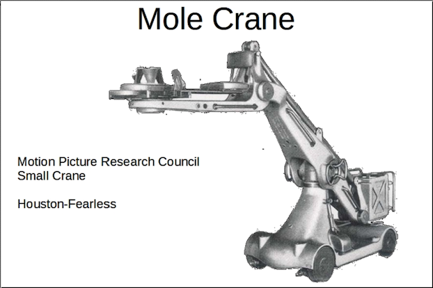
Mole-Richardson (another US company better known for lighting equipment) was licensed to build it in the UK (where it became the “Mole”), although the BBC Tech Ops management hierarchy it was always referred to as the MPRC Crane! The BBC – very civil-service, and acronym, oriented!
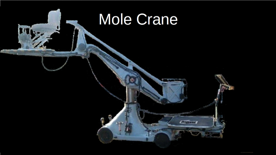
As such, the Mole was, at basis, a motion picture crane. A short-wheelbase dolly had a central pillar (which could be raised) on which was pivoted a counterbalanced arm. At one end there was a platform for the cameraman and focus puller (and at a pinch, the director), at the other a large bucket full of lead weights. Weights were added to balance the camera and cameraman (and could be pulled out to provide extra leverage).
In the film industry – and in the United States television studios – the counterbalanced arm was manhandled by grips or wranglers holding onto the front of the arm and walking with the crane. Initially the steering was by a tiller.
(Grip: a person who works primarily on the complex equipment which supports the cameras and on lighting.
Wrangler: a person who professionally searches for and/or handles particular products on film and television programs. The word “wrangler” is derived from the Low German “wrangeln” meaning “to dispute” or “to wrestle”. It was first documented in 1377. Its use as a noun was first recorded in 1547.)
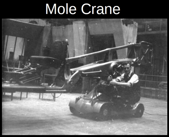
The Mole Crane went though a number of iterations to adapt it for television use. Firstly, the forward and rear drive was controlled from a precariously tiny seat fixed halfway down the right hand side of the Mole at the base of the jib support column.
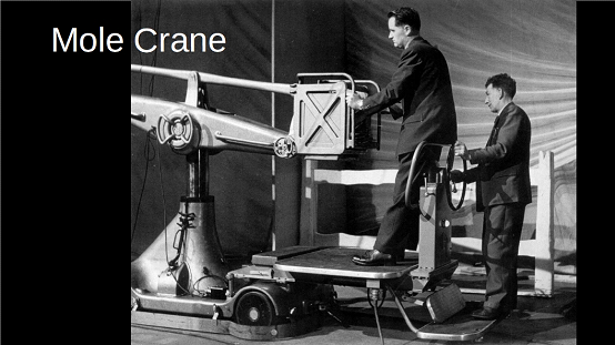
A platform was built so that a “swinger” could control the counterbalanced arm from the rear. This required a four-man crew.
In its final form, a further platform was added to the rear for the driver, who steered the whole thing and controlled the speed and direction. By this time, the overall length was some 18 ft 1 inch. The turning radius was some 11 feet. The weight of the crane (without camera and crew) was 4490lbs -approximately 2.25 tons.
There was a solenoid which operated a brake on the jib arm or boom if cameraman go off the seat without the crane jib being locked off.
The clearest illustration of a Mole crane in full cry is this one from The Readers’ Digest Junior Omnibus.
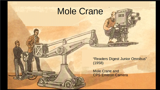
The Mole crane was a tricky beast – it was very versatile but needed excellent cooperation between three people. The large overhang of the swinger platform and the tracker (Driver) platform made steering and controlling the thing quite tricky in difficult situations. And with a top speed of over 8 miles per hour – more than 12 feet per second – in a confined space – it was fast.
The Motion Picture Research Council crane chassis was second cousin to a fork lift truck. It was mounted on four large solid rubber wheels, and, as it did not have any springs, it did not have any suspension, except for any compliance provided through the drive mountings and by the wheels. One Tech Ops person has suggested that there was about a half-inch play in the chassis. The front wheels were driven through a differential, rumoured to be from an early Ford motor car with a worm drive from a 110 volt DC motor. The axle layout very much resembled that used on contemporary fork lift trucks, with solid fork lift type wheels, and similar drive flanges from the half shafts. The original half-shafts were meant to break and had a weak weld at the wheel end. That made it easy to pull out the broken one from the outside rather than dismantle the axle. Bill Marshall, then Head of Mechanical Workshop towards the end of the Mole’s life in the studios, had new half shafts fabricated at great expense from [quote] really modern steel [unquote] as the Light Entertainment crews were regularly breaking the shafts: after the change, they never broke another one. Bill also commented he could not get any more differentials, but the existing ones evidently were in pristine condition.
The rear steering axle resembled a cast beam axle found on earlier cars (before the days of independent suspension) but as it was only approximately 3 ft wide, it was not simply lifted – again, it may have been taken from a fork-lift truck design or similar.
There were occasions when a Mole driving wheel was spinning due to the floor not being level and a non-existent Mole crane suspension. On one occasion, the variation in floor level in the studio was measured. This turned out to be greater than the depth of the topping, so the sub-floor had to be to blame. The studio floors at Television Centre were originally quarter-inch thick linoleum on an asphalt base screed straight onto the concrete floor slab in Television Centre (the asphalt acted as a shock absorber and was easier to level than concrete in those days), but later (after my time, probably after 1972) this was changed to self-levelling resin. The linoleum was always being damaged. The real killer of the lino floors was the overnight floor wash which allowed watery gunge to seep under the lino tiles either at the edges or from a divot (from a scenery scrape, dropped stage weight or screw caught in a Mole or Heron cable guard).
The 110 volt DC supply terminated in a Kliegl connector, the width of which limited the amperage that could be taken from the socket. So a pup or a soft light could be plugged in to the same socket as the crane but in theory the socket could not be overloaded. For reasons of safety the supply was 55 volts positive and 55 volts negative which meant that in theory at least no one could get a lethal shock.
Like all other cables in the BBC, the Mole power cable had to be tied off where the supply fed into the Kliegl connector. For if this connection was broken, there was no power to the crane – which meant no control over the crane: it would just lumber on…
The Mole crane arm could crane down to a lens height of 2 feet or crane up to a height of 10 feet. The versatility of the Mole crane was such that many directors would use the crane to track in or out, crane up or down on shot for some time without cutting to another camera. In motion, on shot, it could be an imposing sight.
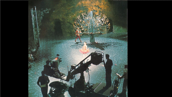
The Mole was used on many different types of programmes: here a three very different productions.
This last shot shows me tracking the Mole Crane on “Top of the Pops” in 1965. Ron Green is the Senior Cameraman up front.
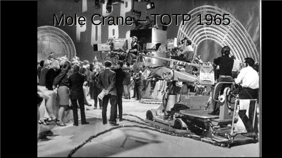
The group in the background is…?
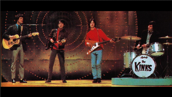
The Kinks – as shown of one of their album covers .
Chapman Hercules Camera Crane
About 1950, Chapman developed a crane than could travel independently. The cranes were equipped with petrol engines so they could be taken to the location under their own power. The unit was mounted on a chassis that could also run on a silent electric motor drive for use on sets using recording takes using sensitive sound equipment. This electric drive was used when the crane came into the televisions studios.
On petrol, it could travel anywhere. The crane was no longer confined to the sound stage, it could travel with the production and shoot exteriors from city streets to deserts and mountains. And wherever the set was they could be set up to do all the things they had been doing on the stage or backlot including a six-wheel crab ability.
Designed by Ralph Chapman for Paramount Pictures, Chapman built the crane for Demille’s Paramount production of “The Greatest Show on Earth” (1950) – one of first “road trips” that took the unit out of Hollywood was for De Mille’s circus extravaganza when it was used to film actual circus performances in Washington, DC. The crane was designed to be more than a one-off: Cecil B. De Mille used it on his re-make of “The Ten Commandments” (1952).
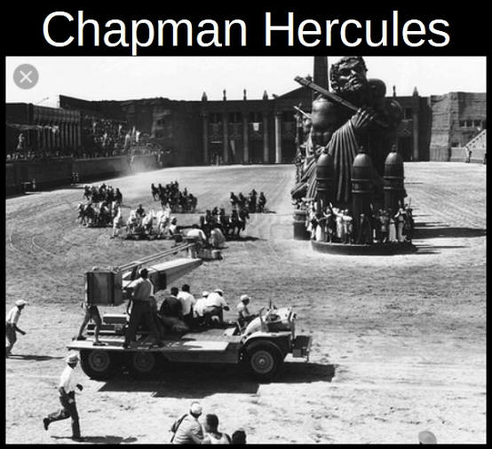
After the success of the device, Chapman improved upon his design and developed it into product named “Hercules.” These units were available for hire by anyone. Here is a Hercules used on the chariot race in “Ben Hur”:– there is a persistent rumour that the scream as a grip fell of the crane when travelling at speed was kept in the final cut.
When the “Hercules” was used in the Television Centre, it came with its own driver – he did the tracking: however, two guys from the Tech Ops crew had to steer the thing – one on each side, one facing the rear. Also Tech Ops guys had to swing the arm.
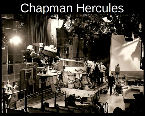
I worked on a couple of shows with the “Hercules” crane – the second one was an episode of “the Country and Western Show” – a summer time version the show we cannot name! The director was – Stewart Morris.
Transatlantic
A later development of the “Hercules” was the “Transatlantic”. The Transatlantic had a lattice jib arm, and like the Hercules, also came with its own driver (or tracker). The steering – front wheels steer or back wheels steer according to which direction the crane was travelling – was operated by BBC Tech Ops, one on each side of the crane body.
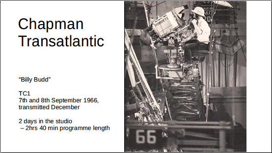
There was not enough room in most TV studios to utilise this crane fully with the exception of TC1 -or possibly Studio G at Lime Grove.
And now…
Camera cranes are relegated to speciality use now. With the invention of the Louma crane and the Technocrane, camera cranes were replaced by robotic jib arms or computer controlled units that could repeat the same move over and over again. Then, as video cameras got smaller and smaller, the miniaturization of high quality cameras made the need of a person operating a camera thirty feet in the air unnecessary. Today, with the proliferation of drones, the days of land based cranes of any sort are numbered.
Finally….
A typical use of a camera crane in BBC days of the 1960s Light Entertainment was the “end of the show” shot – on a light entertainment program, the camera would start tight on a close-up of a performer, then track back and crane up at speed to reveal the complete cast and set.
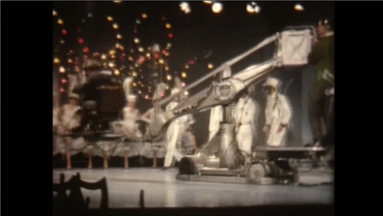
Here we see the Mole crane going in for the close up, and then tracking out and craning up for that all=important high angle wide shot – on a programme we no longer dare to name …
| Video Clip | |
| To see a video clip which was displayed with this slide, please click on the centre arrow below: |
Acknowledgements
My thanks to all those who have helped with material for this presentation, including Bernie Newnham Roger Bunce, Dudley Darby, Brian Phillips, Derek Blackman, Alan Taylor Graeme Wall, Nick Ware Patrick Heigham (for the Mole in action shot) and all of the contributors to the BBC TV Tech Ops web site and email group Ross Millard (Vitec Group)
 |  |