
Day 1
Tuesday …
Yawn, get up, get out of bed…
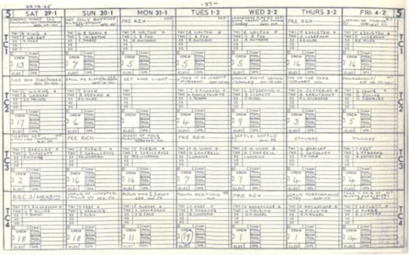
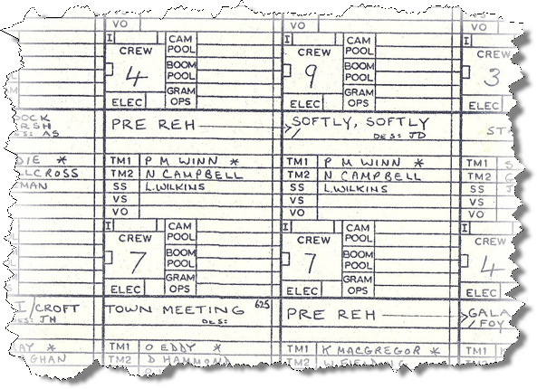
The TODS (Technical Operations Duty Schedule) released some four weeks ago had marked this Tuesday and Wednesday as two days in the Studio TC3 for Crew 7 to work on “Softly, Softly” – so it showed the days the crew was working: and you may like to note that, just like the “Radio Times”, the BBC week began on a Saturday!
Four weeks before…
So those two days were marked out in each individual crew member’s diary.
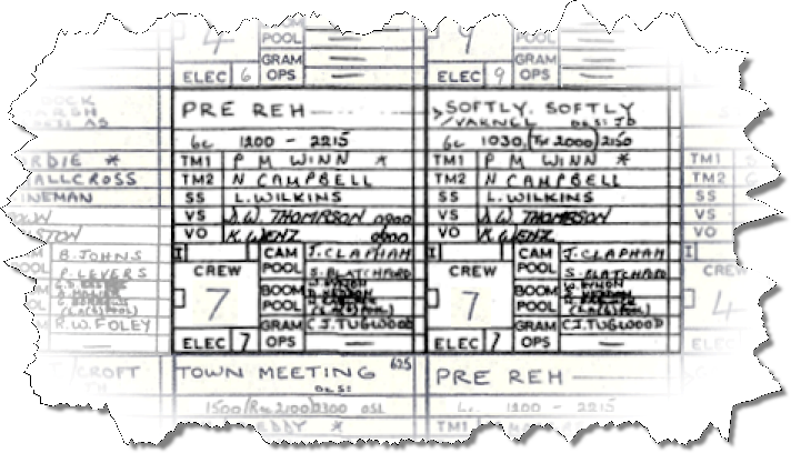
Then two weeks to go, the appropriate issue of the TODS showed the times that the crew had to report to the studio for the week. For this episode of “Softly, Softly”, the Tuesday call was for 12 o’clock midday (12:00).
Two weeks before
So the times now got entered into the diary. Some people liked the diaries, kept them to remember what programmes they had worked on – others, when they left Technical Operations, wanted never to have to be tied to diary ever again!
The scheduling at this time in the BBC (mid-nineteen-sixties) was straightforward. If a programme was 30 to 45 minutes long, or less, such as a situation comedy (sit com), it had one day in the studio (although some programmes, such as Schools programmes and “Play School” might do two programmes in one day) – and the crew start time was usually half-past nine in the morning (09:30). If the programme duration on transmission was between fifty minutes and one hour or so, the programme got two days in the studio. If it was longer than one hour, it got three days in the studio. Programmes such as “The Wednesday Play” ran for anything up to 100 minutes, so had three days in the studio: these were generally known as “three-day plays”. For the drama series, the actors reported to the studio on what might be called “theatre time” – later mornings, afternoon rehearsal, evening performance! But of course, everyone in television had to be flexible.
So getting up on the Tuesday morning was no problem – up at about 7 o’clock to 7:30 am (07:00 to 07:30), as usual: get washed and dressed – white shirt, tie, charcoal grey trousers (NO jeans!) and Desert Boots: it was a requirement to wear soft-soled shoes in the studios, and Technical Operators got a clothing allowance (“soft soled shoe allowance”) to pay for them. Jacket, shirt and tie! But that was what was expected of professional people….Then a reasonable time for breakfast as the members of the crew didn’t need to be in the studio until 12 o’clock midday (12:00). A nice easy start to the day,
The studio Technical Operators worked irregular hours – this was officially noted in many of the employment documents. Irregular hours could mean an early start, or a call to the studios for mid-afternoon (for transmission to the United States during the night). It meant weekend working but also free time when everyone else was at work. Today it is an easy drive – leave home about half-past ten (10 thirty am: 10:30) – well past the rush hour, so not too many cars about.
Drive up to Shepherd’s Bush – and then try to park the car. The favourite place to park is Frithville Gardens, which leads up from Uxbridge Road to the rear entrance of Television Centre. Of course, by this time of day all the parking spaces have been taken.
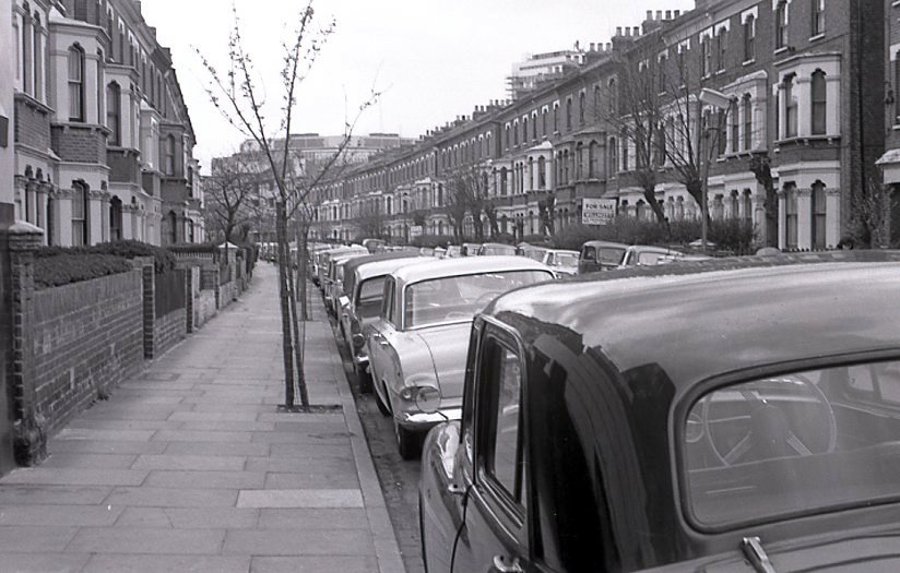
As I couldn’t park there, it was a case of driving round the roads North of the Uxbridge Road and towards the West – getting closer and closer to Loftus Road, the home of Queen’s Park Rangers Football Club – notorious in those days for bad behaviour by the fans.
Finally, I find a space to park the car, so now have to walk down the streets to Uxbridge Road, then walk up Frithville Gardens to the Television Centre.
If you wanted to get to TV Centre using public transport, you could catch the Metropolitan line from Paddington down to Shepherds’ Bush, travelling past Ladbroke Grove and Latimer Road and past Studio TC1 of the Television Centre (opened a couple of years earlier in April 1964). (In 1988 this branch of the Metropolitan got renamed to its former name of the Hammersmith and City Line, but even in 1966 it was known as the “Hot and Cold”.) Shepherd’s Bush station was on the Television Centre side of Uxbridge Road, so again it was a walk up Frithville Gardens and in via the back entrance.
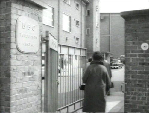
Just to the left of this entrance is the entrance to Hammersmith Park. No walk in the park, today!
In through the back gate and head for Studio 3 – security? What security? Just walk in, past the scenery block, up the road to the outer ring road …
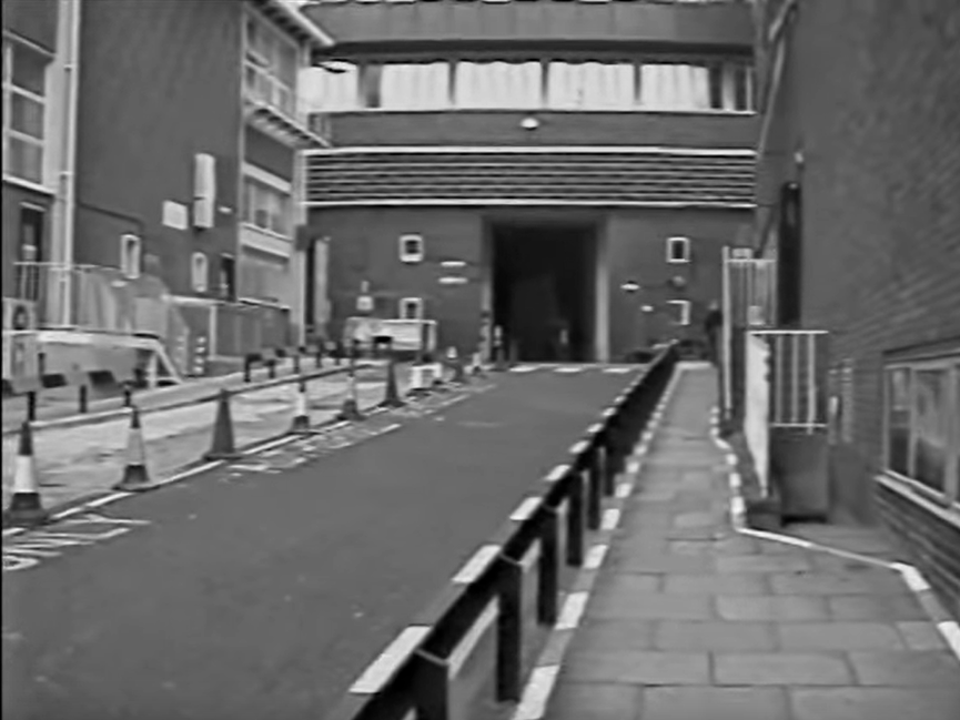
Rumble, rumble, rumble, rumble, to-ooo-oot… (and an occasional crackle) from a Metropolitan line underground (subsurface) train on the viaduct on its way from Shepherd’s Bush station.
TC3 was actually 1 foot narrower than the otherwise matching TC4 because the walls of TC3 were thicker so that there would less noise from the Metropolitan line underground trains which passed quite close to the Television Centre – and there was a whistle board (telling the drivers to sound their “whistle”) just to add to the noise!
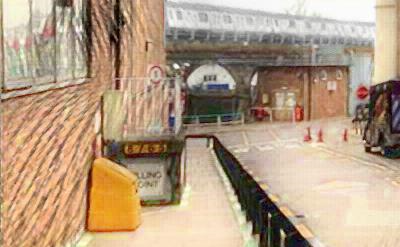
Cross the outer ring road, then inside Television Centre. Cross the scenery runway – the covered ring “behind” the studios – in which were parked scenery trucks, equipment moved out of a studio, some things covered with tarpaulin…
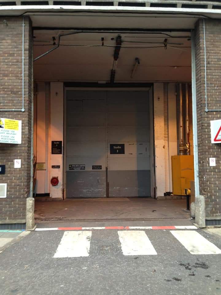
Go across the scenery runway – then though the studio double doors and there you are, in Studio 3 (TC3).
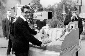
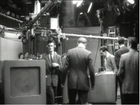
“It’s a Square World”
It is usually Studio 3 for drama, as Studio 4 is equipped with Ambiophony (the only studio so equipped at the time) and is earmarked for musical productions when necessary, although TC4 is also used for the whole range of programmes which need a large studio space (such as Michael Bentine’s “It’s a Square World”: the marks on the studio walls made by that show could still be seen years later …). The EMI 203 camera is equipped with an Angenieux Zoom lens.
Walk the length of the studio. past all the sets (scene set overnight) and then up the stairs into the gallery, through the Lighting and Production galleries to the crew room, which was located behind the production gallery itself. The crew room is an odd -shaped room. Just like many of the rooms in Television Centre – the studios had right angles in the corners, but few of the other rooms did! Hang jacket on a peg, go into the gallery where some of the crew had already gathered – say “Hello” or “Good Morning!”, Then all down to the studio floor.
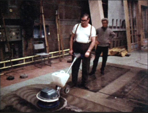
Cleaning the Studio Floor [Roger Bunce
The studio has been set overnight for this episode of “Softly, Softly” The previous programme in TC3 (an episode of “Dixon of Dock Green”) was recorded on to Videotape (VT) starting at 17:30 – and lasted until 20:45 – plenty of time for retakes! The crew had finished the equipment derig by 9 o’clock pm (21:00). So then the scene crew could strike the “Dixon of Dock Green” sets, wash the studio floor and following that, together with the Sparks (in charge of positioning the lights according to the plan), do the overnight set and light (OSL) for “Softly, Softly”.
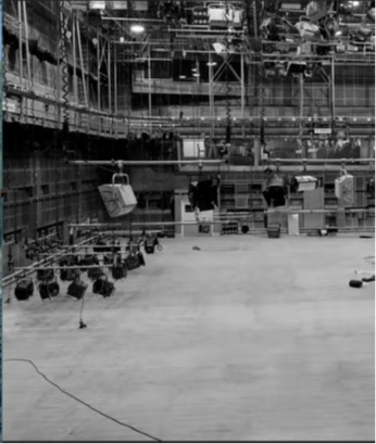
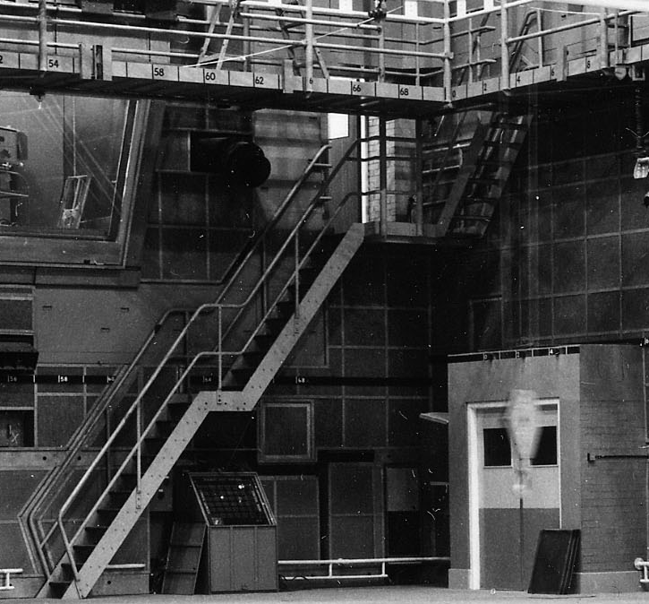
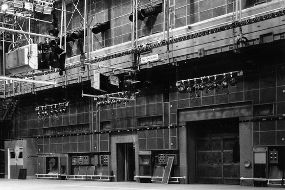
Ready for Overnight Set and Light, Studio TC3
Greet all the other members of the studio crew. Look at the sets.
Ah, good, there is a “practical” pub set (“practical” means that a prop (property) actually works as it supposed to: in this case, there are practical beer engines that will actually pull a pint!). Most of the props are in place already, and where necessary the studio floor has been painted. The studio floor needs to be flat and completely even for the camera pedestals and cranes to work, so paving stones, carpets, parquet flooring are all just painted onto the studio floor with water-based paint.
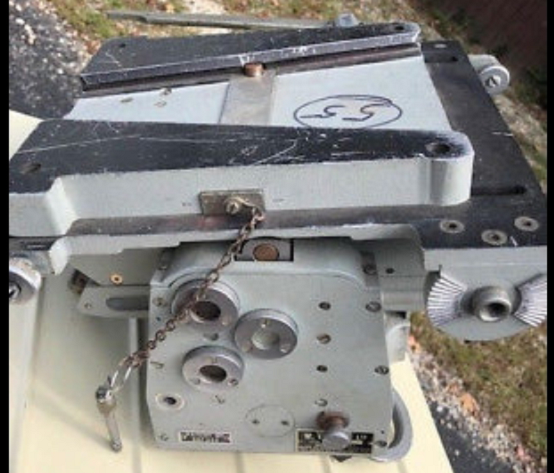
The crew head for the studio’s Tech Store (technical equipment storeroom). The Television Centre Studios have special rooms for the store of technical equipment, but in Lime Grove Studios and the TV Theatre the cameras are left in place in the studio. What equipment do we need today? If a crane was needed for the show, it would almost certainly be a Vinten Heron crane – it would unlikely to be a Mole crane (the Mole-Richardson Motion Picture Research Council Crane) on “Softly, Softly” as there is not a lot of studio space left between the sets for a crane of its size. There is a smaller crane – the Vinten Motorised, but this crane does not have the elevation of a Heron and it cannot crab (that is, go sideways (track sideways)). It does, however, have a tight turning circle. The Heron lacks the flexibility and fluidity of the large Mole crane, but it is pretty versatile – and has been specifically designed for television work.
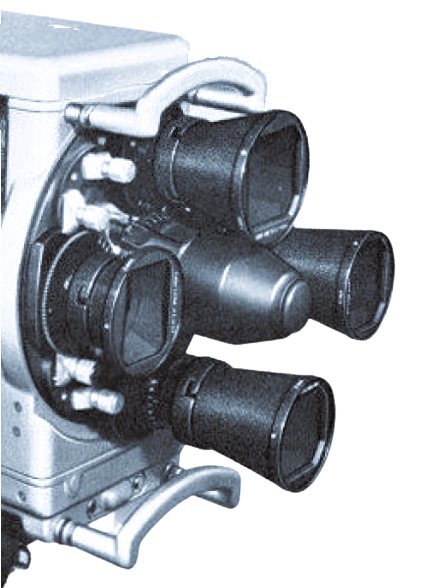
The cameras in Studio 3 are Marconi Mk IV 4.5-inch Image Orthicon cameras – these are nicer to operate than the EMI 203 cameras in TC4 (Television Centre Studio 4), as they have a much smoother lens change.
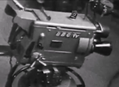
The cameras are turret cameras, that is, the camera has four lenses of different focal lengths mounted on the front: the turret is rotated by a lens change handle mounted on the side of the camera, above the focus capstan.
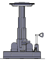
Make sure that each camera needed was on its appropriate mount: most of them are to be mounted on a Vinten Hydro-Pneumatic (HP) pedestal (it has hydraulic rams pressurised by nitrogen stored in cylinders at the base of the pedestal).
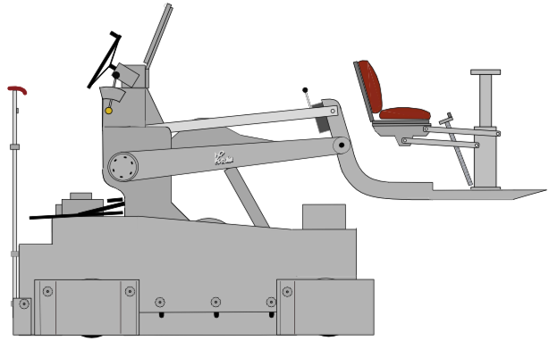
Checking with the equipment manifest and the studio plan for the episode, it is clear that a Vinten Heron crane is to be used. The crew are hoping for a specific Heron: the crews got to know their numbers (each crane is identified by a number painted on the rear). The crane is intended to be driven using the hand controllers for acceleration, speed and direction, but many trackers prefer to use the Emergency cut-off valve – foot operated – to start the track and to control the speed. Some machines have valves which seem to operate in a progressive manner, rather than ON/OFF, and in fact later versions of the Heron crane did in fact use a progressive hydraulic valve on this foot control. The crew (at least, those who are likely to be assigned to track the Heron) sigh with relief when they recognise the one to use today.
Camera 1 is mounted on the crane.
Each camera is secured to its pan and tilt head by a wedge plate on the bottom, the wedge plate secured by a locking bar and the locking bar secured by a pin. This actually acts as a quick-release mechanism, as the camera could be released from the pan and tilt head very quickly. Make sure the head is locked off before removing or mounting a camera! On many pan and tilt heads there are chains to keep the head locked in place.
Wheel the Heron crane and each of the other cameras on their Vinten HP pedestals onto the studio floor, and move each camera to its first position as marked on the studio plan – this plan shows each camera position throughout the show. Each camera is identified by its cue light (1, 2 3 and so on), and so camera 1 on the Heron crane has to go to the position 1A on the plan for camera 1. There are occasions when camera cue lights are removed or changed round (this latter requiring some re-pluggery by the studio engineers) , but this is rare and certainly not done on “Softly, Softly”.
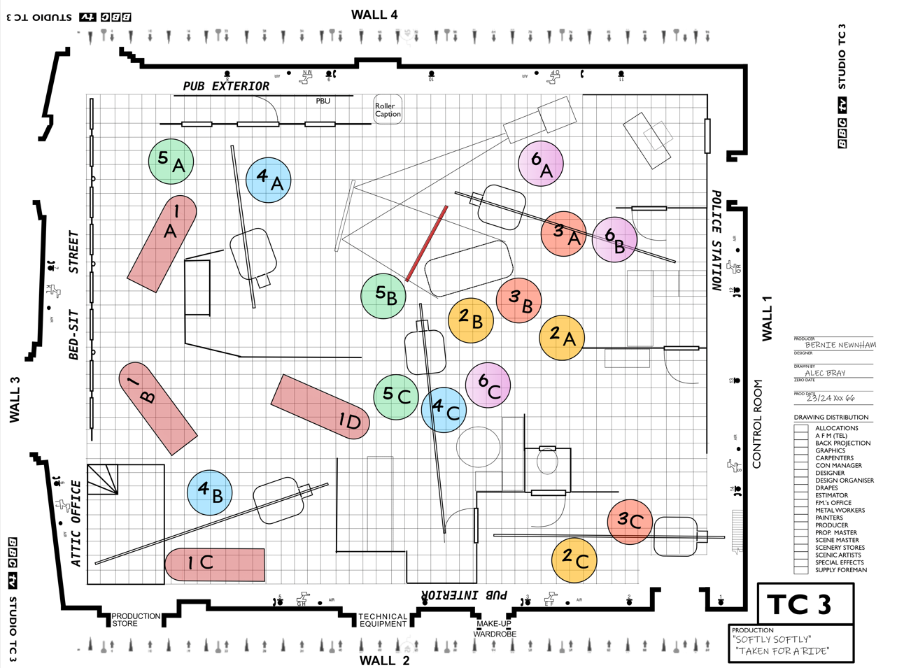
(some equipment positions omitted for clarity)
Note: There are no publicly available or accessible copies of studio production plans for any programmes in TC3 (or for any of the Television Centre studios) for this period – (there is one floor plan for TC1 – a “Doctor Who” episode. – but for well after this period). This Artist’s Impression is a fabrication for illustrative purposes only.
The next job is to drag out the camera cables. These cables are thick, covered in sharp dust, and any slack in the cable is “coiled” as a figure-of-eight.
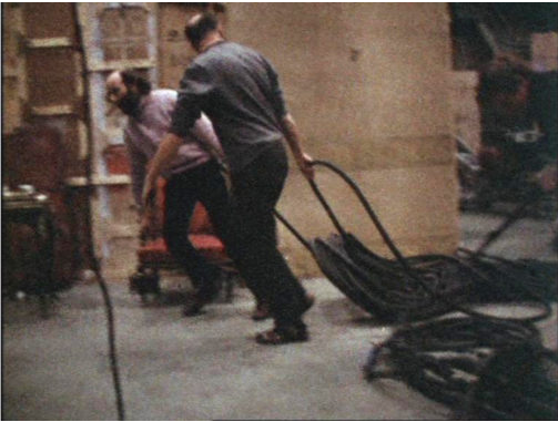
The camera cable for each camera is inserted into the camera’s cable mounting and the ring tightened. The cable has to be clamped to the cable clamp at the bottom of the pedestal with enough cable at the camera end to allow the Vinten pedestal (“ped”) to go to its maximum height and the camera to pan fully down – and to be able to pan left and right.
The other end of the camera cable has to connect to one of the wall points around the studio. Once again, reference to the studio plan should indicate which one of the wall points should be used for each camera, so that during the production the camera cables would not get knotted together as the cameras moved – not always possible, though! A good director tried hard to work out camera positions and cable routings to prevent any problems with cable: one director used matchboxes to represent the camera and string to represent the cables.
It also depends on the sorts of shots that each camera is expected to be able to offer: a camera with a zoom lens, for example, or one mounted on a crane could offer very specific shots. So sometimes, even with the best directors, there were times when the camera cables crossed: a camera would have to “duck under” the crossing cable!
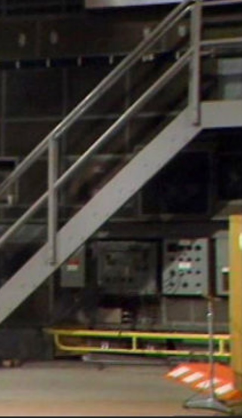
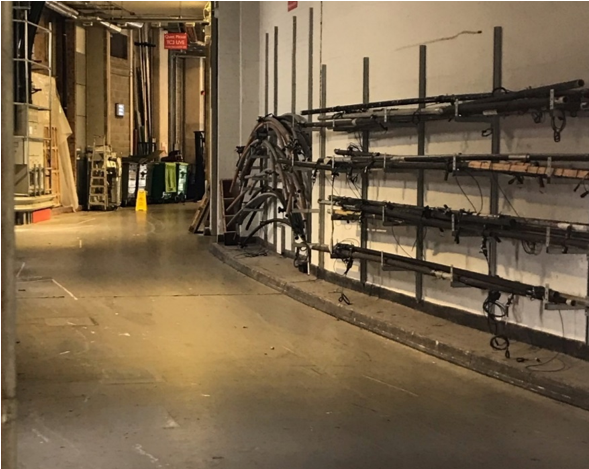
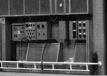
Studio Wall point and fire ramp
The free end of the cable is taken from the bottom of the figure-of-eight and led across the studio, under the yellow bar at the bottom of the studio wall and then up to connect with one of the camera outlets on the wall point – each one was labelled – A, B and so on round the studio.
The fire ramp has to be put over the cable so that the fire lanes around the studio periphery had all cables covered.
Fire Officers will patrol round the studio to make sure that all fire regulations are being adhered to – no one is allowed to smoke in the studios, for example, except for those actors who need to smoke as part of their act. No equipment or coils of cables are allowed in the fire lanes around the periphery of the studio. All cables, with the exception of the thick camera cables, also have to be tied off, and all cables have to be covered with the fire ramps.
Occasionally for some episodes, a camera ped is to be used on a rostrum, so the ped (and camera) has to be hoisted onto this. The scene hoists are operated by the scene crew, so they are in charge of getting the pedestal onto the rostrum: technical operators lifted the camera onto the rostrum, and then onto the ped itself. On one or two episodes, the camera might be mounted on a scaffolding tower in the studio, so that the camera could get a high angle shot of the people in the set. A likely shot would be of a prisoner in a cell. In this case, the riggers would have built the scaffolding tower and fastened a pan-and-tilt head to the correct edge of the tower, along the waist-height safety rail, during part of the overnight set and light (OSL). Technical Operators would work with the scene crew to get the camera – and the camera end of the camera cable – up to the tower staging, from where the technical operators would rig the camera as normal. The cameraman gained access to the camera by climbing a ladder fixed to the tower. It was rare on a drama series like “Softly, Softly” to have such a tower, as it took up valuable studio floor space, but sometimes the story line demanded it.
Usually there are at least 5 of the cameras rigged on the studio floor, as described. In theory, camera 6 (in TC3 and TC4) was a “hot standby” mounted on a trolley placed somewhere accessible in the studio and cabled up with the other cameras. If a camera failed “on-air” (that is, when the programme was being transmitted live to people’s television sets), the hot standby could be swapped for the failed camera on its original mount. As the cameras could not be disconnected from their cables until the studio engineers (“Racks”) had made the camera electrically and electronically stable, it was often easier to quickly get another camera to cover the failed camera’s shots. So the hot standby wasn’t needed – so the camera could now be mounted on a pedestal and fully incorporated as a working camera 6 in the script. More flexibility. So six cameras would be fully rigged. The proviso was that, if any camera failed, there would no longer be a working spare, nor any guarantee that the failed camera would be fixed during the transmission (live transmission or “as-live” recording).
If the camera is to have lighting “headlights” (either two small bulbs in reflective housing mounted on the front of the camera below the lens (or a single light mounted above the lens turret) to light up an actor’s face or pick out the highlights in his or her eyes), the power cable has to be fed to the camera. This is a “standard” 13-amp flexible extension-lead power cable, and it has to be wrapped around the camera cable – the whole length of the camera cable, usually. So, starting from the camera, wind about 5 feet of power cable anticlockwise round the camera cable, and fasten the two cables together with camera tape. Then wind the power cable alternately clockwise and anti-clockwise down the camera cable, and secure the two together with camera tape at each change of winding direction down the whole length of the camera cable to the edge of the studio floor.
Camera tape is white open-weave canvas sticky-backed tape (only available in white, so of course it shows up clearly if a camera cable gets into shot), and a couple of turns of this sticky tape usually suffices to secure the cables. It is tough, durable and long-lasting – but white…
 Winding a power cable round a camera cable |  Camera tape |
The power cables are also fed under the thick yellow bar at the studio walls, but are tied off on the smaller yellow bar above. The knot is usually a looped half-hitch, such that the cable pulls tight from the studio floor side but can be released quickly from the plug side.
Some of the power cables had lethal plugs on the end – this was before the standard “square” pin MK plugs.
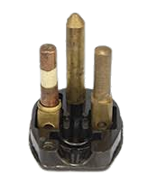
D&S plug
These Dorman and Smith plugs had been used in London County Council housing projects from 1948, and other authorities followed soon. The one advantage was that it was simple to replace a blown fuse – simply unscrew the pin, insert a new one. Unfortunately a fuse could become unscrewed on its own in use, ending up protruding from the socket. Since the fuse is the line (live) pin, it was easy to get an electric shock. The fuse would remain in the power outlet when you pulled out the plug….
(There were also the “Chinese” plugs, similar to the MK but with the earth pin horizontal rather than vertical! It was someone’s bright idea to reduce pilferage of MK plugs.)
If two cables need to be joined together (in cases where one cable was too short), the ends of the cable are tied with a reef knot before being joined together using the plug and socket. The whole idea of cables being tied down is that they will not separate or be pulled out of the wall socket during the programme, or generally pulled out of position. (This applies as well to cables used for sound: a free-standing mic has its cable tied off to a suitable leg, brace or stand at floor level. If the mic is on a mic stand, the cable is taped to the stand top and bottom to make it more elegant. Some C-stands have a spiral metal cable restraint at the bottom which allowed the cable to slip through as the stand is raised or lowered by a performer. This system works OK when mic is raised but usually leaves a loop when the mic is lowered!)
The Heron crane needs its power supply, too: this is a somewhat thicker power cable, but this also has to be wound round the camera cable and secured by camera tape (again, first wound clockwise with the end of the section fixed with camera tape, then the next section wound anti-clockwise, fixed, and so on). It is important to get the auxiliary cables wound tight against the main camera cable, so that there are no loose loops that could get caught under the cable guards of the pedestals or cranes. The Heron power supply is similarly looped under the lower yellow bar round the studio side walls – but in this case the cable also has to be tied off to the bar above before being connected to the 230V A.C. 3 phase supply with its heavy metal 5-pin plug and securing ring.
To let the actors, floor managers – and particularly the microphone boom operators – see what the cameras are seeing, a number of monitors have to be rigged in the studio, typically one per set. Likely positions are identified, and the video feed and power supply cables are wound together (clockwise then anticlockwise alternately down the length of the cable), fed under the fireboards, under the yellow bar, independently tied off on the small bars attached to the studio wall boxes, and then independently plugged into the power supply and video feed. Video cables have F & E plugs that utilised threaded connectors, slower but more substantial than the later BNC connectors.
As some of the scenes in the programme have already been shot on film (location Outside Broadcasts for Drama productions was an extremely rare event), there may be a couple of monitors specifically rigged to show the telecine output – the telecine machines used to show photographic 35mm or 16 mm film on television were located at Lime Grove and at Television Centre, and the machine used for the film inserts could come from either location. Film inserts are usually used, as a Telecine (TK) machine already has to be booked for the two days of rehearsal and transmission, because the programme titles are on film. A Videotape (VT) insert would tie up a video-tape machine for two days, as the replay schedule depended on how the rehearsals were progressing. There are, however, quite a few “Softly, Softly” episodes where VT is used, adding to the joys of the Vision Control operator! Telecine machines are always known throughout productions, studio management and operations as “TK” – because “TC” (a more common abbreviation in other organisations for TeleCine) was used in the BBC for “Television Centre” – as in studio TC3. TC3 is a studio: TK3 is a telecine machine.
On some rigs, one or more of the cameras would need something extra – a long-focus lens, for example, or a zoom lens. These are kept in Technical Stores, up on the second floor of Television Centre (the third floor was where Wardrobe and Makeup were located). One of the crew is sent up to stores – probably the Crew Relief Mainly Cameras. One thing that is always needed from stores is Camera Tape. Usually the storemen were dour and generally jobsworths – “you can have one reel” – but occasionally they would delight you by being very helpful – and giving you more than you really needed! One this day, Camera 5 is going to have a zoom lens. There are two types of Zoom lenses available at this time. A Taylor, Taylor and Hobson (TTH) mechanically operated Varotal 2 zoom, and an Angenieux servo controlled, 10:1 range zoom (wider wide angle, narrower telephoto). Because of its weight, the Angenieux zoom lens also has supporting stays which fix to the top of the camera, replacing the front carrying handle on the Marconi Mk. IV, and also need a tray bolted to the side of the pan and tilt head to hold a sizeable box which contains all the servo electronic controls. Today the camera is to have the TTH zoom – and like all the special lenses, this has to be booked out from Technical Stores. All the store requisitions, except for “consumable” items such as Camera Tape, have had to be requisitioned from Stores by the Technical Manager 2 some days before, although, this being live television and with live television needs, there is always some flexibility in getting items on the day itself. So, collect the items from stores, down in the scenery/props lift (especially if there was a trolley full of bits from stores) – back into the studio to complete the rig.
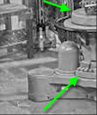
Blanking plates fixed to cover unused lens positions
Camera 5 has its lenses removed, and the TTH zoom mounted into the lens mounting at the bottom of the turret – this lines up with the image orthicon tube. Blanking plates are fixed to cover the other lens positions. Like everything to do with the camera mounting (except the cable entry which fastened with a screw collar), the lens clips are quick release, so they can be changed quickly if need be – just two quarter-turn clips each side of the lens mounting block, with single locking knobs. The lenses fitted to the mounts are fixed focus, and so are easy to change. For these lenses, focus is achieved by moving the Image Orthicon (IO) tube forward and back inside the camera. A zoom lens is a different matter. At this time, the zoom lenses are varifocal. You have to zoom out to a wide shot, and set focus using the IO tube – and then use the friction brake to lock the tube in position (and hope it stayed “locked” (it didn’t always…). Then you zoom in to a close-up of the object which is the main subject of the shot, and set focus on that object using the zoom lens focus. Each shot with a zoom needs a refocus of the zoom lens in this way.
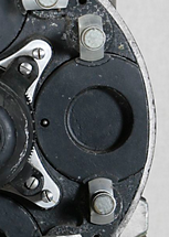
“Trimming” lead weights carried in trays cast into the base of the pedestal.
The weight of the zoom lens – together with its hand controls – is a different total weight to the four fixed lenses: so with the TTH Varotal zoom in place, the weight on the top of the Vinten Pedestal is different. As the pedestal is kept at the required heigh by balancing the downward forces (gravity) by the (upward) pressure of compressed nitrogen (by means of the hydraulic rams), the weight on top has to be correct. To allow for variations in the weight of the camera and its lenses, “trimming” lead weights are carried in trays cast into the base of the pedestal. These weights can be added to (or removed from) a tray at the top of the Vinten pedestal columns. (If the weight change is significant, Maintenance need to be called to repressurise the nitrogen held in two of the three vertical cylinders on the base of the pedestal: the other cylinder holds the hydraulic fluid.)
Meanwhile, the three sound assistants on the crew have been just as busy. The Fisher microphone booms have to be got out of the technical storeroom – hopefully before the camera cables had been plugged in, otherwise the booms have to bounce over the camera cables.
The standard microphone for television drama and series before this time had been the STC 4033 – actually designed by the BBC, but the BBC was not allowed to manufacture, so the design was handed over to STC (Standard Telephone and Cables). The 4033 microphones were actually two microphones stuck together: a ribbon and a moving coil mic.
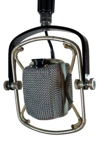
AKG D-25 Microphone
With the Fisher Booms, a different mic is used – the AKG D-25: this microphone has been specially designed for Film and Television work. It is mounted in a cradle with elastic suspension, allowing the mic to be disengaged from the potentially interfering vibrations from the boom movement and racking in and out of the boom arm. The D 25 has a filter to cut off the lowest frequencies, so that the mic could be spun around with even less extraneous noise on a quiet set in the TV studio. In the TV studios, the majority of microphones used are cardioid mics, to mask out as much studio sound behind the cameras as possible. These D-25 mics have to be collected from Technical Stores on the second floor, together with any special sound equipment.
There is often a need for a special microphone to use in a particular situation: in this case, there is – unusually – a closed set, that is, a set with all four walls (made from theatre type scenery flats). It is impossible to get a normal microphone boom into this small, enclosed cubicle. So the Sound Supervisor has decided to sling an omni-directional microphone from the upper gantry to suspend over the centre of the cubicle. So the sound assistant has to collect an STC 4021 omnidirectional “apple and biscuit” microphone from stores: it was called an “apple and biscuit” because that is just what it looked like, a round biscuit stuck onto an apple.
The starting position for each boom is marked on the studio floor plan, so each mic boom is moved to the correct position. The sound assistants mount a D-25 microphone in the cradle of each boom – the booms are already strung with microphone cable running round the pulleys at the rear of the boom. The other end of this laced cable is connected to a standard mic cable, which is then fed under the studio bars, tied off and plugged into one of the microphone sockets in the wall point
To cope with the film inserts, a couple of foldback speakers need to be placed in position: these have a feed of telecine sound and are plugged into a line output on the wall point, the power supply plugged in, and the cables tied off.
One of the Sound Assistants has the interesting job of mounting the STC 4021 omni-directional mic over the closed, four-wall set – this set was for a lavatory cubicle (a WC).
The easiest way of mounting this is to sling the microphone from a suitable scenery hoist, and feed its long cable to the nearest point on the studio’s first level gantry, where the cable is tied off, before being fed along and across the gantry to one of the wall points on the wall of the gantry , where it is to be tied off again and connected into one of the mic sockets. To do this needs liaison with the scene crew to get access to the scene hoists.
(The alternative is to sling the mic down from the studio ceiling grid, but this needs a lot more cable, and it causes a problem if the position of the mic needs to be adjusted during the rehearsals. In theory – in the rule book – this slung microphone should have been rigged by the riggers.)
 |  |  |